CY3263-COLORLOCK Cypress Semiconductor Corp, CY3263-COLORLOCK Datasheet
CY3263-COLORLOCK
Specifications of CY3263-COLORLOCK


Related parts for CY3263-COLORLOCK

CY3263-COLORLOCK Summary of contents
Page 1
... CY3263-ColorLock EZ-Color™ Evaluation Kit Guide Doc. # 001-44081 Rev. *A Cypress Semiconductor 198 Champion Court San Jose, CA 95134-1709 Phone (USA): 800.858.1810 Phone (Intnl): 408.943.2600 http://www.cypress.com ...
Page 2
... Code protection does not mean that we are guaranteeing the product as "unbreakable." Cypress is willing to work with the customer who is concerned about the integrity of their code. Code protection is constantly evolving Cypress are committed to continuously improving the code protection features of our products. 2 CY3263-ColorLock EZ-Color Evaluation Kit Guide, Doc. # 001-44081 Rev. *A ...
Page 3
... Add Five Interface Valuators .....................................................................................27 3.6 Define Output Behavior .............................................................................................29 3.7 Add an Interface Driver ..............................................................................................30 3.8 Build project ...............................................................................................................30 3.8.1 Build the Project .............................................................................................30 3.9 Program the EZ-Color Part ........................................................................................32 3.10 Tune Your Project......................................................................................................32 3.11 Calibrate the LEDs.....................................................................................................33 CY3263-ColorLock EZ-Color Evaluation Kit Guide, Doc. # 001-44081 Rev ...
Page 4
... Add Seven State Machine Transitions ...................................................................... 59 5.10 Define Output Behavior ............................................................................................. 60 5.11 Add an Interface Driver..............................................................................................61 5.12 Build project............................................................................................................... 61 5.13 Program the EZ-Color Part........................................................................................ 63 5.14 Tune Your Project...................................................................................................... 63 5.15 Calibrate LEDs .......................................................................................................... 63 5.16 Run Program ............................................................................................................. 64 4 CY3263-ColorLock EZ-Color Evaluation Kit Guide, Doc. # 001-44081 Rev ...
Page 5
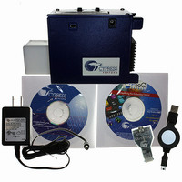
... LEDs can be used in a design, depending upon the application and the desired color gamut. Right out of the box, CY3263-ColorLock EZ-Color Evaluation kit can be used to evaluate and dem- onstrate EZ-Color functionality, including color mixing and optical feedback. See the quick start on how to use the kit with the factory installed firmware ...
Page 6
... When prompted that the USB Mini Programmer (x.x.x.x) software has not passed Windows Logo Testing, click Continue Anyway. 8. When Windows has completed the installation, click Finish. 6 CY3263-ColorLock EZ-Color Evaluation Kit Guide, Doc. # 001-44081 Rev. *A PSoC Step 3. to the latest version avail- ...
Page 7
... The On/Off Button The CY3263-ColorLock EZ-Color evaluation hardware has two buttons and a liquid crystal display. These allow the board to be demonstrated without using a personal computer to control the board. When held properly for use, the buttons liquid crystal display face upward. When held in this orienta- tion, the right-most button alternately turns the high brightness LEDs on and off. The default setting when power is applied is off ...
Page 8
... Note: To add a driver to a design, you must open a new or existing project. Adding new drivers does not work in the Start Page in PSoC Express. 8 Figure 1-2 on page Digital Output Banked Output Field User Input XLeds 4 Strong (default) CY3263-ColorLock EZ-Color Evaluation Kit Guide, Doc. # 001-44081 Rev. *A 9). The driver blocks are then ...
Page 9
... Note: Some of the projects in this guide will not work unless the Add Driver Dialog option is selected. Figure 1-3. Use Add Driver Dialog Menu Option is Selected CY3263-ColorLock EZ-Color Evaluation Kit Guide, Doc. # 001-44081 Rev. *A 1-2) is visible not visible, select View → Driver (Figure ...
Page 10
... Design (Figure Figure 1-4. Adding a Driver Via Drag and Drop Figure 1-5. Adding a Driver Via the Contextual Menu 10 (Figure 1-4), double-click the item, or right-click on the item and select Add 1-5). CY3263-ColorLock EZ-Color Evaluation Kit Guide, Doc. # 001-44081 Rev. *A ...
Page 11
... Note: If the Actions column in the PSoC Programmer status box indicates “Firmware update required at...”, the MiniProg's firmware is out of date. Before attempting to program the target EZ- Color chip Utilities → Upgrade Firmware to update the MiniProg's firmware. CY3263-ColorLock EZ-Color Evaluation Kit Guide, Doc. # 001-44081 Rev. *A Introduction (Figure 1-6) ...
Page 12
... Represents menu paths: File → Open → New Project Displays commands, menu paths, and icon names in procedures: Click the File icon and then click Open. Displays an equation Describes Cautions or unique functionality of the product. CY3263-ColorLock EZ-Color Evaluation Kit Guide, Doc. # 001-44081 Rev. *A ...
Page 13
... Tuner in PSoC Express, which is a design tool, and will not function while PSoC Express is open. The CY3263-ColorLock EZ-Color Evaluation Kit board demonstrates the ability of a EZ-Color con- troller to provide closed-loop, high accuracy control for three primary, high brightness LEDs to create mixed-color output ...
Page 14
... Windows, as well as at least 1.5 megabytes of available hard disk space. In addition, one available USB port is needed to connect the evaluation board to the computer using mini B USB cable. This port can be provided by using an expansion hub connected to one of the host computer’s USB ports. 14 CY3263-ColorLock EZ-Color Evaluation Kit Guide, Doc. # 001-44081 Rev. *A ...
Page 15
... Connected to ColorLock Demonstration, along with the version of the ColorLock unit’s firmware. The status box background changes to green to indi- cate that communication has been established (see Figure 2-1. The ColorLock Startup Display CY3263-ColorLock EZ-Color Evaluation Kit Guide, Doc. # 001-44081 Rev. *A ColorLock Monitor Figure 2-2). ...
Page 16
... If color-lock has been turned off (i.e., the red ‘X’ to the right of the green arrow) the LEDs are also turned off. Figure 2-2. Connected to the ColorLock Hardware 16 CY3263-ColorLock EZ-Color Evaluation Kit Guide, Doc. # 001-44081 Rev. *A ...
Page 17
... Figure 2-3. CIE 1976 Color Display CY3263-ColorLock EZ-Color Evaluation Kit Guide, Doc. # 001-44081 Rev. *A 2-3). When turned off, the corresponding graph trace is removed from the ColorLock Monitor Figure 2-3) ...
Page 18
... See Figure 2-4. Figure 2-4. Running Monitor Showing the Three Graphs Actively Charting 18 in the tool bar (see Section 14 selecting the pull-down labeled Monitor and clicking and select- CY3263-ColorLock EZ-Color Evaluation Kit Guide, Doc. # 001-44081 Rev. *A 2.3.2 Toolbar Icons and ...
Page 19
... CIE related controls, become inactive. The LEDs are controlled by setting the PrISM values directly using the slider for each LED so ColorLock functionality no longer applies. See Figure 2-5. Feedback Disabled CY3263-ColorLock EZ-Color Evaluation Kit Guide, Doc. # 001-44081 Rev. *A ColorLock Monitor Figure 2-5. ...
Page 20
... Application Note (Help → About) This menubar selection results in a pop-up window that displays the application version and copyright information. Clicking the OK button closes the About window. 20 44533 ColorLock Optical Feedback for CY3263-ColorLock EZ-Color Evaluation Kit Guide, Doc. # 001-44081 Rev. *A EZ-Color. ...
Page 21
... ColorLock unit is not attached. Figure 2-6. Error Reading Calibration Matrices CY3263-ColorLock EZ-Color Evaluation Kit Guide, Doc. # 001-44081 Rev. *A ColorLock Monitor Figure 2-6 shows the result of ...
Page 22
... A similar error occurs if sensor calibration is attempted without an attached ColorLock unit. See Figure 2-7. If this error occurs, the ColorLock unit can be attached and the calibration values are retained so that the calibration can be completed without entering the values again. Figure 2-7. Calibration Failure 22 CY3263-ColorLock EZ-Color Evaluation Kit Guide, Doc. # 001-44081 Rev. *A ...
Page 23
... Reset the Board to the Original Factory Programming Follow these steps if you wish to reset the board to the original factory installed programming: 1. Locate the CY3263-ColorLock CY8CLED16.hex file on the ColorLock CD included with this kit the following directory: D:\Firmware\Hex Files\CY3263-ColorLock CY8CLED16.hex 2. To reset the board to the factory conditions, connect your computer to the Color- Lock main board ISSP Connector (J4) using the PSoC MiniProg and a USB cable ...
Page 24
... ColorLock Monitor 24 CY3263-ColorLock EZ-Color Evaluation Kit Guide, Doc. # 001-44081 Rev. *A ...
Page 25
... LM3404 Switching Regulators to power the LEDs. 3.2 EZ-Color Device CY8CLED16, 48-Pin MLF 3.3 Start a New Project 1. Select File → New Project. 2. Name the project Tuner needed, click Browse to save the project in a different location. 4. Click OK. CY3263-ColorLock EZ-Color Evaluation Kit Guide, Doc. # 001-44081 Rev ...
Page 26
... Luxeon Rebel® with LM3402 Field User Input ColorLock 20000 1931 XYZ Color Space LXML-PD01 Red LXML-PM01 Green LXML-PB01 Blue Yes CY3263-ColorLock EZ-Color Evaluation Kit Guide, Doc. # 001-44081 Rev. *A Properties win- (Default) (Default) (Default) (Default) (Default) (Default) (Default) (Default) (Default) (Default) (Default) (Default) ...
Page 27
... Interface Valuator is initially placed in the design. Table 3-2. Discrete Interface Valuator Driver/Valuator Discrete Valuators Tab Location Name Properties Default Value States CY3263-ColorLock EZ-Color Evaluation Kit Guide, Doc. # 001-44081 Rev. *A Rebel with 3402) Properties Window ® Interface (Communication) Valuators Discrete Field User Input LEDEnable 0x1 ...
Page 28
... User Input LEDBrightness -32767 32767 1 750 Interface (Communication) Valuators Discrete Field User Input LEDTrigger 0x1 Interface (Communication) Valuators Continuous Field User Input xValuator -32767 32767 1 2000 CY3263-ColorLock EZ-Color Evaluation Kit Guide, Doc. # 001-44081 Rev. *A (Default) (Default) (Default) (Default) (Default) (Default) (Default) ...
Page 29
... Set Target y to yValuator ■ Set Relative Flux to LEDBrightness ■ Set ColorLock Trigger to LEDTrigger ■ Figure 3-2. ColorLock Transfer Function Window 3. Click OK when done. CY3263-ColorLock EZ-Color Evaluation Kit Guide, Doc. # 001-44081 Rev. *A Interface (Communication) Valuators Continuous Field User Input yValuator -32767 32767 ...
Page 30
... Flash Interface → ■ 4. Ensure the Assign pins automatically check box is not selected. 5. Click Next the User Pin Assignment window, click Unassign All Pins. 30 Communication I2C Slave Field User Input Interface1 4 → Enable CY3263-ColorLock EZ-Color Evaluation Kit Guide, Doc. # 001-44081 Rev. *A (Default) ...
Page 31
... Figure 3-4. Tuner Pinout Diagram 8. Select Lock Pins, and click Next. PSoC Express builds your project. CY3263-ColorLock EZ-Color Evaluation Kit Guide, Doc. # 001-44081 Rev. *A Table 3-8 Table 3-8, not the order of appearance in the User Pin Assign- Function 0 ColorLock_ColorSensor Port 2_5 7 TCS230SHARED_0 S0 Port 2_0 ...
Page 32
... Select Monitor in PSoC Express. Figure 3-5. PSoC Express Monitor Pane 4. Click Play . The Monitor toolbar will change from Connected 5. Right-click on the ColorLock driver icon and select Show Tuner. 32 Program Parts with PSoC Express Projects section CY3263-ColorLock EZ-Color Evaluation Kit Guide, Doc. # 001-44081 Rev Running . ...
Page 33
... Enter coordinates directly into the x and y fields. 9. Click directly within color gamut. 10. Click Lock Color. 11. Click any other point inside color gamut and watch optical feedback response. CY3263-ColorLock EZ-Color Evaluation Kit Guide, Doc. # 001-44081 Rev. *A Rebel with LM3402) Tuner ® Tuner Project ...
Page 34
... Tuner Project 34 CY3263-ColorLock EZ-Color Evaluation Kit Guide, Doc. # 001-44081 Rev. *A ...
Page 35
... LM3404 Switching Regulators to power the LEDs. 4.2 EZ-Color Device CY8CLED16, 48-Pin MLF 4.3 Start a New Project 1. Select File → New Project. 2. Name the project TrafficLight needed, click Browse to save the project in a different location. 4. Click OK. CY3263-ColorLock EZ-Color Evaluation Kit Guide, Doc. # 001-44081 Rev ...
Page 36
... Luxeon Rebel® with LM3402 Field User Input ColorLock 20000 1931 XYZ Color Space LXML-PD01 Red LXML-PM01 Green LXML-PB01 Blue Yes CY3263-ColorLock EZ-Color Evaluation Kit Guide, Doc. # 001-44081 Rev. *A Properties win- (Default) (Default) (Default) (Default) (Default) (Default) (Default) (Default) (Default) (Default) (Default) (Default) ...
Page 37
... Table 4-2. Discrete Interface Valuator Driver/Valuator Discrete Valuators Tab Location Interface (Communication) Valuators Name Properties Default Value States CY3263-ColorLock EZ-Color Evaluation Kit Guide, Doc. # 001-44081 Rev. *A Rebel with 3402) Properties Window ® Discrete Field User Input LEDEnable 0x1 Traffic Light Project ...
Page 38
... Click Add State, set the Name to Yellow, and click OK. 38 Continuous Field User Input LEDBrightness -32767 32767 1 1000 Discrete Field User Input LEDTrigger 0x1 StateMachine Field User Input TrafficState CY3263-ColorLock EZ-Color Evaluation Kit Guide, Doc. # 001-44081 Rev. *A (Default) (Default) (Default) (Default) ...
Page 39
... The Priority Encoder Transfer Function - xValuator window opens. Set the If/Else statements to the values in Table Table 4-7. xValuator Priority Encoder Transfer Function Values TrafficState_state==TrafficState_state__Green TrafficState_state==TrafficState_state__Red TrafficState_state==TrafficState_state__Yellow CY3263-ColorLock EZ-Color Evaluation Kit Guide, Doc. # 001-44081 Rev. *A PriorityEncoder Field User Input xValuator 4-7. Else/If ...
Page 40
... Table 4-9. yValuator Priority Encoder Transfer Function Values TrafficState_state==TrafficState_state__Green TrafficState_state==TrafficState_state__Red TrafficState_state==TrafficState_state__Yellow 2. Select Continuous. Figure 4-4. Priority Encoder Transfer Function - yValuator Window 40 PriorityEncoder Field User Input yValuator 4-9. Else/If CY3263-ColorLock EZ-Color Evaluation Kit Guide, Doc. # 001-44081 Rev. *A Then yValuator = 5000 3000 4200 ...
Page 41
... Table Table 4-12. RedCount Priority Encoder Transfer Function Values (TrafficState_state==TrafficState_state__Red) && (Count100ms==Count100ms__Triggered) TrafficState_state!=TrafficState_state__Red Figure 4-5. Priority Encoder Transfer Function - RedCount CY3263-ColorLock EZ-Color Evaluation Kit Guide, Doc. # 001-44081 Rev. *A Interval Generator Field User Input Count100ms 100 (Default) ...
Page 42
... Table 4-14. GreenCount Priority Encoder Transfer Function Values (TrafficState_state==TrafficState_state__Green) && (Count100ms==Count100ms__Triggered) TrafficState_state!=TrafficState_state__Green Figure 4-6. Priority Encoder Transfer Function - GreenCount 2. Click OK when finished. 42 PriorityEncoder Field User Input GreenCount 4-14. Else/If CY3263-ColorLock EZ-Color Evaluation Kit Guide, Doc. # 001-44081 Rev. *A Then GreenCount = GreenCount+1 0 ...
Page 43
... Table 4-16. YellowCount Priority Encoder Transfer Function Values (TrafficState_state==TrafficState_state__Yellow) && (Count100ms==Count100ms__Triggered) TrafficState_state!=TrafficState_state__Yellow Figure 4-7. Priority Encoder Transfer Function - YellowCount 2. Click OK when finished. CY3263-ColorLock EZ-Color Evaluation Kit Guide, Doc. # 001-44081 Rev. *A PriorityEncoder Field User Input YellowCount 4-16. Else/If ...
Page 44
... Click OK. 44 LCD LCD Selectable Scrolling Text - Full Line Field User Input LCDText No_Text Row 0 Stop Go Slow Down! (Leave Blank) (Leave Blank) (Leave Blank) (Leave Blank) 100 Text1 Text2 Text3 CY3263-ColorLock EZ-Color Evaluation Kit Guide, Doc. # 001-44081 Rev. *A (Default) (Default) (Default) ...
Page 45
... Right Click Green and select Edit. 2. Click Add the Name field, enter GreenYellow the Expression field, enter GreenCount>=50. 5. Set Transition From field to Green, and Transition To field to Yellow. 6. Click OK to close the Add Transition window. CY3263-ColorLock EZ-Color Evaluation Kit Guide, Doc. # 001-44081 Rev. *A Traffic Light Project 45 ...
Page 46
... Set Transition From field to Yellow, and Transition To field to Red. 6. Click OK to close the Add Transition window. Figure 4-11. Add Transition Window 7. Click OK to close the Add State window. 8. Click OK to close the State Machine Transfer Function TrafficState window. 46 CY3263-ColorLock EZ-Color Evaluation Kit Guide, Doc. # 001-44081 Rev. *A ...
Page 47
... Table 4-18. Slave Driver Driver/Valuator I2C Slave Interface Interfaces Tab Communication Location Properties Name I2C_Address With a little rearranging, your workspace should look like the example in CY3263-ColorLock EZ-Color Evaluation Kit Guide, Doc. # 001-44081 Rev. *A I2C Slave Field User Input Interface1 4 (Default) Traffic Light Project Figure 4-13 ...
Page 48
... Traffic Light Project Figure 4-13. PSoC Express Design View Pane 48 CY3263-ColorLock EZ-Color Evaluation Kit Guide, Doc. # 001-44081 Rev. *A ...
Page 49
... Assignment window. Table 4-19. TrafficLight Pinouts Order of Order of Assignment Appearance CY3263-ColorLock EZ-Color Evaluation Kit Guide, Doc. # 001-44081 Rev. *A → Enable Table 4-19, not the order of appearance in the User Pin Function 0 ColorLock_ColorSensor 7 TCS230SHARED_0 S0 8 TCS230SHARED_0 S1 9 TCS230SHARED_0 S2 10 TCS230SHARED_0 S3 1 ColorLock_Enable 2 ColorLock_Dim1 3 ColorLock_Dim2 4 ...
Page 50
... Disconnect any power sources from the evaluation board and connect the MiniProg to your PC using a USB cable. 2. Connect the Miniprog to the 5-pin ISSP header. 3. Program the part via J1 as described in the on page 11. 50 Program Parts with PSoC Express Projects section CY3263-ColorLock EZ-Color Evaluation Kit Guide, Doc. # 001-44081 Rev. *A ...
Page 51
... Click OK to return to the Tuner. 4.18 Run Program Uncheck Override to observe the TrafficLight program. After closing the tuner window, power cycle the evaluation board before continuing with monitoring or tuning the design. CY3263-ColorLock EZ-Color Evaluation Kit Guide, Doc. # 001-44081 Rev. *A Traffic Light Project , to Running . 51 ...
Page 52
... Traffic Light Project 52 CY3263-ColorLock EZ-Color Evaluation Kit Guide, Doc. # 001-44081 Rev. *A ...
Page 53
... LM3404 Switching Regulators to power the LEDs. 5.2 EZ-Color Device CY8CLED16, 48-Pin MLF 5.3 Start a New Project 1. Select File → New Project. 2. Name the project ModulatedDimmer needed, click Browse to save the project in a different location. 4. Click OK. CY3263-ColorLock EZ-Color Evaluation Kit Guide, Doc. # 001-44081 Rev ...
Page 54
... Luxeon Rebel® with LM3402 Field User Input ColorLock 20000 1931 XYZ Color Space LXML-PD01 Red LXML-PM01 Green LXML-PB01 Blue Yes CY3263-ColorLock EZ-Color Evaluation Kit Guide, Doc. # 001-44081 Rev. *A Properties win- (Default) (Default) (Default) (Default) (Default) (Default) (Default) (Default) (Default) (Default) (Default) (Default) ...
Page 55
... Interface Valuator is initially placed in the design. Table 5-2. Discrete Interface Valuator Driver/Valuator Discrete Valuators Tab Location Name Properties Default Value States CY3263-ColorLock EZ-Color Evaluation Kit Guide, Doc. # 001-44081 Rev. *A Rebel with 3402) Properties Window ® Interface (Communication) Valuators Discrete Field User Input LEDEnable 0x1 ...
Page 56
... User Input LEDTrigger 0x1 Interface (Communication) Valuators Continuous Field User Input xValuator -32767 32767 1 5000 Interface (Communication) Valuators Continuous Field User Input yValuator -32767 32767 1 2500 CY3263-ColorLock EZ-Color Evaluation Kit Guide, Doc. # 001-44081 Rev. *A (Default) (Default) (Default) (Default) (Default) (Default) (Default) ...
Page 57
... Set the Name to State0. 3. Click OK. 4. Repeat Step 1 through Figure 5-2. State Machine Transfer Function TickState 5. Click OK when finished. CY3263-ColorLock EZ-Color Evaluation Kit Guide, Doc. # 001-44081 Rev. *A Transfer Function Valuators StateMachine Field User Input TickState Step 3, naming the states State1 through State7. ...
Page 58
... LEDBrightness<=0 58 Timing Interval Generator Field User Input Tick 75 PULSE (Default) Transfer Function Valuators PriorityEncoder Field User Input LEDBrightness Table 5-9. Else/If CY3263-ColorLock EZ-Color Evaluation Kit Guide, Doc. # 001-44081 Rev. *A Then LEDBrightness = LEDBrightness-5 LEDBrightness-10 LEDBrightness-20 LEDBrightness-50 LEDBrightness-75 LEDBrightness-100 LEDBrightness-150 LEDBrightness-200 1000 ...
Page 59
... In the Expression field, enter LEDBrightness<=0. 6. Set Transition From field to State0, and Transition To field to State1. 7. Click OK to close the Add Transition window. Figure 5-4. Add Transition Window 8. Click OK to close the Add State window. CY3263-ColorLock EZ-Color Evaluation Kit Guide, Doc. # 001-44081 Rev. *A Modulated Dimmer Project 59 ...
Page 60
... Set Enable to LEDEnable ■ Set Target x to xValuator ■ ■ Set Target y to yValuator Set Relative Flux to LEDBrightness ■ Set ColorLock Trigger to LEDTrigger ■ Figure 5-6. ColorLock Transfer Function Window 3. Click OK when done. 60 CY3263-ColorLock EZ-Color Evaluation Kit Guide, Doc. # 001-44081 Rev. *A ...
Page 61
... Sample Rate ■ Flash Interface → ■ 4. Ensure the Assign pins automatically check box is not selected. 5. Click Next the User Pin Assignment window, click Unassign All Pins. CY3263-ColorLock EZ-Color Evaluation Kit Guide, Doc. # 001-44081 Rev. *A Communication I2C Slave Field User Input Interface1 4 → ...
Page 62
... ColorLock_Dim1 3 ColorLock_Dim2 4 ColorLock_Dim3 6 Interface1 I2CSDAPin 5 Interface1 I2CSCLPin CY3263-ColorLock EZ-Color Evaluation Kit Guide, Doc. # 001-44081 Rev. *A Assign drivers according to the Pin Notes Port 2_5 Port 2_0 The these four drivers are assigned automatically when Port 2_1 the ColorLock_ColorSensor driver is assigned. You must ...
Page 63
... Calibrate LEDs 1. Select Calibration. 2. Select Set LED1 to Maximum. 3. Select Set LED2 to Maximum. 4. Select Set LED3 to Maximum. 5. Select Calibrate. CY3263-ColorLock EZ-Color Evaluation Kit Guide, Doc. # 001-44081 Rev. *A Program Parts with PSoC Express Projects section Rebel with LM3402) Tuner ® Modulated Dimmer Project , to Running ...
Page 64
... Modulated Dimmer Project 5.16 Run Program Uncheck Override to observe the ModulatedDimmer program. After closing the tuner window, power cycle the evaluation board before continuing with monitoring or tuning the design. 64 CY3263-ColorLock EZ-Color Evaluation Kit Guide, Doc. # 001-44081 Rev. *A ...