CP2104EK Silicon Laboratories Inc, CP2104EK Datasheet - Page 12
CP2104EK
Manufacturer Part Number
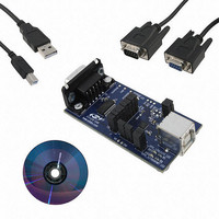
CP2104EK
Description
KIT EVAL FOR CP2104
Manufacturer
Silicon Laboratories Inc
Specifications of CP2104EK
Main Purpose
Interface, USB 2.0 to UART (RS485) Bridge
Embedded
No
Utilized Ic / Part
CP2104
Primary Attributes
Full Speed (12Mbps)
Secondary Attributes
LED Status Indicators
Interface Type
RS-232, USB
Operating Supply Voltage
3.3 V
Product
Interface Development Tools
For Use With/related Products
CP2104
Lead Free Status / RoHS Status
Lead free / RoHS Compliant
Lead Free Status / RoHS Status
Lead free / RoHS Compliant
Other names
336-2007


CP2104
6.1. Baud Rate Generation
The baud rate generator is very flexible, allowing the user to request any baud rate in the range from 300 bps to
2 Mbps. If the baud rate cannot be directly generated from the 48 MHz oscillator, the device will choose the closest
possible option. The actual baud rate is dictated by Equation 1 and Equation 2.
Most baud rates can be generated with an error of less than 1.0%. A general rule of thumb for the majority of UART
applications is to limit the baud rate error on both the transmitter and the receiver to no more than ±2%. The clock
divider value obtained in Equation 1 is rounded to the nearest integer, which may produce an error source. Another
error source will be the 48 MHz oscillator, which is accurate to ±0.25%. Knowing the actual and requested baud
rates, the total baud rate error can be found using Equation 3.
7. GPIO Pins
The CP2104 supports four user-configurable GPIO pins for status and control information. Each of these GPIO
pins are usable as inputs, open-drain outputs, or push-pull outputs. Three of these GPIO pins also have alternate
functions which are listed in Table 11.
By default, all of the GPIO pins are configured as a GPIO input. The configuration of the pins is one-time
programmable for each device. The difference between an open-drain output and a push-pull output is when the
GPIO output is driven to logic high. A logic high, open-drain output pulls the pin to the VIO rail through an internal,
pull-up resistor. A logic high, push-pull output directly connects the pin to the VIO voltage. Open-drain outputs are
typically used when interfacing to logic at a higher voltage than the VIO pin. These pins can be safely pulled to the
higher, external voltage through an external pull-up resistor. The maximum external pull-up voltage is 5 V.
The speed of reading and writing the GPIO pins is subject to the timing of the USB bus. GPIO pins configured as
inputs or outputs are not recommended for real-time signalling.
More information regarding the configuration and usage of these pins can be found in “AN144: CP21xx
Customization Guide” and “AN223: Port Configuration and GPIO for CP210x” available on the Silicon Labs
website.
12
Clock Divider
Actual Baud Rate
=
----------------------------------------------------------------------------------------------------
2 Prescale
=
Baud Rate Error (%)
---------------------------------------------------------------------------- -
2
Prescale Clock Divider
Table 11. GPIO Pin Alternate Functions
Equation 3. Baud Rate Error Calculation
48 MHz
Requested Baud Rate
Equation 1. Clock Divider Calculation
GPIO Pin
48 MHz
Equation 2. Baud Rate Calculation
GPIO.0
GPIO.1
GPIO.2
=
100
RS-485 Transceiver Control
Rev. 1.0
1
Alternate Function
–
---------------------------------------------------------- -
Requested Baud Rate
Prescale
Prescale
RX Toggle
Actual Baud Rate
TX Toggle
Prescale
Prescale
=
=
=
=
4 if Requested Baud Rate 365 bps
1 if Requested Baud Rate 365 bps
4 if Requested Baud Rate 365 bps
1 if Requested Baud Rate 365 bps
0.25%
Related parts for CP2104EK
Image
Part Number
Description
Manufacturer
Datasheet
Request
R

Part Number:
Description:
QFN 24/-40 TO 85 OC/USB TO UART BRIDGE
Manufacturer:
Silicon Laboratories Inc
Datasheet:

Part Number:
Description:
IC SGL USB-TO-UART BRIDGE 24QFN
Manufacturer:
Silicon Laboratories Inc
Datasheet:
Part Number:
Description:
SMD/C°/SINGLE-ENDED OUTPUT SILICON OSCILLATOR
Manufacturer:
Silicon Laboratories Inc
Part Number:
Description:
Manufacturer:
Silicon Laboratories Inc
Datasheet:
Part Number:
Description:
N/A N/A/SI4010 AES KEYFOB DEMO WITH LCD RX
Manufacturer:
Silicon Laboratories Inc
Datasheet:
Part Number:
Description:
N/A N/A/SI4010 SIMPLIFIED KEY FOB DEMO WITH LED RX
Manufacturer:
Silicon Laboratories Inc
Datasheet:
Part Number:
Description:
N/A/-40 TO 85 OC/EZLINK MODULE; F930/4432 HIGH BAND (REV E/B1)
Manufacturer:
Silicon Laboratories Inc
Part Number:
Description:
EZLink Module; F930/4432 Low Band (rev e/B1)
Manufacturer:
Silicon Laboratories Inc
Part Number:
Description:
I°/4460 10 DBM RADIO TEST CARD 434 MHZ
Manufacturer:
Silicon Laboratories Inc
Part Number:
Description:
I°/4461 14 DBM RADIO TEST CARD 868 MHZ
Manufacturer:
Silicon Laboratories Inc
Part Number:
Description:
I°/4463 20 DBM RFSWITCH RADIO TEST CARD 460 MHZ
Manufacturer:
Silicon Laboratories Inc
Part Number:
Description:
I°/4463 20 DBM RADIO TEST CARD 868 MHZ
Manufacturer:
Silicon Laboratories Inc
Part Number:
Description:
I°/4463 27 DBM RADIO TEST CARD 868 MHZ
Manufacturer:
Silicon Laboratories Inc
Part Number:
Description:
I°/4463 SKYWORKS 30 DBM RADIO TEST CARD 915 MHZ
Manufacturer:
Silicon Laboratories Inc