73050 Pomona Electronics, 73050 Datasheet
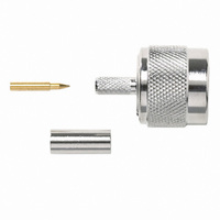
CONN PLUG N STR CRIMP RG58, 141

73050

Manufacturer Part Number
73050
Description
CONN PLUG N STR CRIMP RG58, 141
Manufacturer
Pomona Electronics
Series
N Typer
Type
N Type Plugr
Datasheets

Specifications of 73050

Connector Type
Plug, Male Pins
Impedance
50 Ohm
Connector Style
N Type
Contact Termination
Crimp, Single
Mounting Type
Free Hanging (In-Line)
Fastening Type
Threaded
Cable Group
RG-58, 141
Frequency - Max
6GHz
Frequency-max
6GHz
Body Style
Straight Plug
Coaxial Termination
Crimp
Rg Cable Type
RG-58, 141
Contact Material
Brass
Contact Plating
Gold
Frequency Max
6GHz
Product
Connector
Rf Series
N
Gender
Plug
Polarity
Normal
Shell Plating
Nickel
Termination Style
Crimp
Cable Type
RG/U 58, 141
Housing Material
Brass
Maximum Frequency
6 GHz
Angle
Straight
Finish, Housing
Nickel Plated
Material, Contact
Brass
Material, Dielectric
PTFE
Material, Housing
Brass
Mating Type
Bayonet
Primary Type
N
Voltage, Rating
1500 V
Frequency Range
DC–6 GHz
Insulation Reistance
≤5000 MΩ
Dielectric Withstand Voltage
1500 V
Vswr
≤1.5 V
Number Of Insertions
500 Cycles MinimumFeatures
Connector Accepts Cable Types Rg/u
58, 141
Lead Free Status / RoHS Status
Lead free / RoHS Compliant
Features
-
Color
-
Lead Free Status / Rohs Status
Lead free / RoHS Compliant
www.irf.com
Description
l
l
l
l
l
l
l
l
l
l
Applicable DirectFET Package/Layout Pad (see p.8,9 for details)
Notes  through ˆ are on page 10
V
V
I
I
I
I
P
P
P
T
T
R
R
R
R
R
Absolute Maximum Ratings
Thermal Resistance
D
D
D
DM
J
STG
DS
GS
D
D
D
θJA
θJA
θJA
θJC
θJ-PCB
Application Specific MOSFETs
Integrates Monolithic Trench Schottky Diode
Ideal for CPU Core DC-DC Converters
Low Conduction Losses
Low Reverse Recovery Losses
Low Switching Losses
Low Reverse Recovery Charge and Low Vf
Low Profile (<0.7 mm)
Dual Sided Cooling Compatible
Compatible with existing Surface Mount Techniques
@ T
@ T
@ T
@T
@T
@T
SQ
C
A
A
A
A
C
= 25°C
= 70°C
= 25°C
= 25°C
= 70°C
= 25°C
SD
SX
Drain-to-Source Voltage
Gate-to-Source Voltage
Continuous Drain Current, V
Pulsed Drain Current
Power Dissipation
Power Dissipation
Power Dissipation
Linear Derating Factor
Operating Junction and
Storage Temperature Range
Junction-to-Ambient
Junction-to-Ambient
Junction-to-Ambient
Junction-to-Case
Junction-to-PCB Mounted
ST
Parameter
Parameter
ij
g
g
fj
gj
hj
MQ
GS
GS
GS
HEXFET
@ 10V
@ 10V
@ 10V
MX
®
DS(on)
V
20V
Power MOSFET plus Schottky Diode
DSS
MT
MT
Typ.
12.5
–––
–––
1.0
20
2.5mΩ@V
1.8mΩ@V
R
-40 to + 150
DS(on)
Max.
0.022
180
260
±12
2.8
1.8
20
32
26
89
GS
GS
max
= 4.5V
= 10V
Max.
–––
–––
–––
IRF6691
1.4
45
DirectFET™ ISOMETRIC
rr
Qg(typ.)
47nC
Units
Units
W/°C
°C/W
11/16/05
°C
W
V
A
1

Related parts for 73050

73050 Summary of contents

Page 1

Application Specific MOSFETs l Integrates Monolithic Trench Schottky Diode l Ideal for CPU Core DC-DC Converters l Low Conduction Losses l Low Reverse Recovery Losses l Low Switching Losses l Low Reverse Recovery Charge and Low Vf l Low Profile ...

Page 2

Static @ T = 25°C (unless otherwise specified) J Parameter BV Drain-to-Source Breakdown Voltage DSS ∆ΒV /∆T Breakdown Voltage Temp. Coefficient DSS J R Static Drain-to-Source On-Resistance DS(on) V Gate Threshold Voltage GS(th) ∆V /∆T Gate Threshold Voltage Coefficient GS(th) ...

Page 3

PULSE WIDTH Tj = 25°C 0.1 0 Drain-to-Source Voltage (V) Fig 1. Typical Output Characteristics 1000 100 150° 25° ...

Page 4

0V MHZ C iss = SHORTED C rss = oss = 10000 C iss C oss C ...

Page 5

Case Temperature (°C) Fig 9. Maximum Drain Current vs. Case Temperature 100 D = 0.50 0.20 10 0.10 0.05 1 0.02 0.01 0.1 0.01 ...

Page 6

25° GS, Gate -to -Source Voltage (V) Fig 12. On-Resistance vs. Gate Voltage D.U ...

Page 7

D.U.T + ƒ • • - • + ‚ -  • • • SD • Fig 16. Current Regulator Same Type as D.U.T. 50KΩ .2µF 12V .3µF D.U. 3mA I G Current Sampling Resistors Fig 17. Gate ...

Page 8

DirectFET™ Outline Dimension, MT Outline (Medium Size Can, T-Designation). Please see DirectFET application note AN-1035 for all details regarding the assembly of DirectFET. This includes all recommendations for stencil and substrate designs. IT9(Ã7I TRIFFC AÃ 8CG9 SCI SÃ5R9ÃC ÃGG 8 ...

Page 9

DirectFET™ Board Footprint, MT Outline (Medium Size Can, T-Designation). Please see DirectFET application note AN-1035 for all details regarding the assembly of DirectFET. This includes all recommendations for stencil and substrate designs www.irf.com G = GATE D = ...

Page 10

DirectFET™ Tape & Reel Dimension (Showing component orientation). NOTE: Controlling dimensions in mm Std reel quantity is 4800 parts. (ordered as IRF6691). For 1000 parts on 7" reel, order IRF6691TR1 STANDARD OPTION (QTY 4800) CODE MIN A 330.0 B 20.2 ...

Page 11

DirectFET™ Part Marking Notes:  Repetitive rating; pulse width limited by max. junction temperature. ‚ Starting T = 25° 0.72mH 25Ω 26A ƒ Pulse width ≤ 400µs; duty cycle ≤ 2%. ...

Page 12

Note: For the most current drawings please refer to the IR website at: http://www.irf.com/package/ ...

Related keywords