GRM31CR61E226KE15L Murata, GRM31CR61E226KE15L Datasheet - Page 88
GRM31CR61E226KE15L
Manufacturer Part Number
GRM31CR61E226KE15L
Description
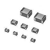
Multilayer Ceramic Capacitors (MLCC) - SMD/SMT 1206 X5R 25V 22uF
Manufacturer
Murata
Series
GRMr
Datasheet
1.GNM1M2R61A105ME14D.pdf
(221 pages)
Specifications of GRM31CR61E226KE15L
Voltage Rating
25 Volts
Operating Temperature Range
- 55 C to + 85 C
Temperature Coefficient / Code
X5R
Product
Automotive MLCCs
Dimensions
1.6 mm W x 3.2 mm L x 1.6 mm H
Termination Style
SMD/SMT
Capacitance
22 uF
Tolerance
10 %
Package / Case
1206 (3216 metric)
Lead Free Status / RoHS Status
Lead free / RoHS Compliant
Available stocks
Company
Part Number
Manufacturer
Quantity
Price
Company:

Part Number:
GRM31CR61E226KE15L
Manufacturer:
MURATA
Quantity:
600 000
Part Number:
GRM31CR61E226KE15L
Manufacturer:
MURATA/村田
Quantity:
20 000


!Note
• This PDF catalog is downloaded from the website of Murata Manufacturing co., ltd. Therefore, it’s specifications are subject to change or our products in it may be discontinued without advance notice. Please check with our
• This PDF catalog has only typical specifications because there is no space for detailed specifications. Therefore, please approve our product specifications or transact the approval sheet for product specifications before ordering.
sales representatives or product engineers before ordering.
!Note
!Note
86
No.
*
14
15
16 Durability
17 ESR
* LLR: This specification is only for LLR Type
LLL/LLR/LLA/LLM Series Specifications and Test Methods (2)
LLL/LLR/LLA/LLM Series Specifications and Test Methods (2)
Continued from the preceding page.
Temperature
Sudden
Change
High
Temperature
High
Humidity
(Steady
State)
1. This Specifications and Test Methods is downloaded from the website of Murata Manufacturing co.,ltd. Therefore, it's specifications are subject to change or our products in it may be discontinued without advance notice.
• Please read rating and !CAUTION (for storage, operating, rating, soldering, mounting and handling) in this catalog to prevent smoking and/or burning, etc.
0.
• This catalog has only typical specifications because there is no space for detailed specifications. Therefore, please approve our product specifications or transact the approval sheet for product specifications before ordering.
2. This Specifications and Test Methods has only typical specifications because there is no space for detailed specifications. Therefore, please approve our product specifications or transact the approval sheet for product
0.
Please check with our sales representatives or product engineers before ordering.
specifications before ordering.
Item
Appearance No marking defects
Capacitance
Change
D.F.
I.R.
Dielectric
Strength
Appearance No marking defects
Capacitance
Change
D.F.
I.R.
Appearance No marking defects
Capacitance
Change
D.F.
I.R.
R6, R7, C7, C8: Within 12.5%
R6, R7, C7, C8: 0.120 max.
50 · F min.
No failure
R6, R7, C7, C8: Within 12.5%
R6, R7, C7, C8: 0.2 max.
12.5 · F min.
R6, R7, C7, C8: Within 12.5%
* LLL153C70G474: Within 20%
R6, R7, C7, C8: 0.2 max.
25 · F min.
Within below ESR value at Frequency: 10 0.1MHz
100m : Within 70 to 130m
220m : Within 154 to 286m
470m : Within 329 to 611m
1000m : Within 700 to 1300m
When no "*" is added in PNs table, please refer to LLL/LLR/LLA/LLM Series Specifications and Test Methods (1).
When "*" is added in PNs table, please refer to LLL/LLR/LLA/LLM Series Specifications and Test Methods (2).
Specifications
Fix the capacitor to the supporting jig in the same manner and
under the same conditions as (10).Perform the five cycles
according to the four heat treatments listed in the following
table. Let sit for 24 2 hours at room temperature,
then measure.
• Initial measurement
Apply the rated voltage at 40 2 C and 90 to 95% humidity for
500 12 hours.
The charge/discharge current is less than 50mA.
Apply the rated DC voltage.
•Initial measurement
•Measurement after test
Apply 150% of the rated voltage for 1000 12 hours at the
maximum operating temperature 3 C.
The charge/discharge current is less than 50mA.
•Initial measurement
•Measurement after test
The ESR should be measured at room temperature with the
Equivalent of HP4294A.
Perform a heat treatment at 150+0/–10 C for one hour and
then let sit for 24 2 hours at room temperature. Perform the
initial measurement.
Perform a heat treatment at 150+0/–10 C for one hour and
then let sit for 24 2 hours at room temperature. Perform the
initial measurement.
Perform a heat treatment at 150+0/–10 C for one hour and
then let sit for 24 2 hours at room temperature, then measure.
Perform a heat treatment at 150+0/–10 C for one hour and
then let sit for 24 2 hours at room temperature. Perform the
initial measurement.
Perform a heat treatment at 150+0/–10 C for one hour and
then let sit for 24 2 hours at room temperature, then measure.
Time (min.)
Temp. ( C)
Step
Min. Operating
Temp. +0/–3
30 3
1
Test Method
Temp.
Room
2 to 3
2
Min. Operating
Temp. +0/–3
30 3
3
Temp.
Room
2 to 3
4
C02E.pdf
10.12.20
Related parts for GRM31CR61E226KE15L
Image
Part Number
Description
Manufacturer
Datasheet
Request
R

Part Number:
Description:
Murata Microblower 20x20 DCDC Driver Board - Samples Only
Manufacturer:
Murata
Part Number:
Description:
357-036-542-201 CARDEDGE 36POS DL .156 BLK LOPRO
Manufacturer:
Murata
Datasheet:
Part Number:
Description:
Manufacturer:
Murata
Datasheet:
Part Number:
Description:
Manufacturer:
Murata
Datasheet:
Part Number:
Description:
Manufacturer:
Murata
Datasheet:
Part Number:
Description:
Manufacturer:
Murata
Datasheet:
Part Number:
Description:
Manufacturer:
Murata
Datasheet:
Part Number:
Description:
Manufacturer:
Murata
Datasheet:
Part Number:
Description:
Manufacturer:
Murata
Datasheet:
Part Number:
Description:
BLM21BD751SN1On-Board Type (DC) EMI Suppression Filters
Manufacturer:
Murata
Datasheet:
Part Number:
Description:
BLM15AG100SN1On-Board Type (DC) EMI Suppression Filters
Manufacturer:
Murata
Datasheet:
Part Number:
Description:
NFE31PT222Z1E9On-Board Type (DC) EMI Suppression Filters
Manufacturer:
Murata
Datasheet:
Part Number:
Description:
Chip Coil
Manufacturer:
Murata
Datasheet:
Part Number:
Description:
Chip Coil
Manufacturer:
Murata
Datasheet: