GRM1885C1H100JA01D Murata, GRM1885C1H100JA01D Datasheet - Page 59
GRM1885C1H100JA01D
Manufacturer Part Number
GRM1885C1H100JA01D
Description
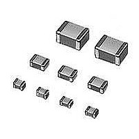
Multilayer Ceramic Capacitors (MLCC) - SMD/SMT 0603 10pF 50volts C0G 5%
Manufacturer
Murata
Series
GRMr
Datasheet
1.GNM1M2R61A105ME14D.pdf
(221 pages)
Specifications of GRM1885C1H100JA01D
Voltage Rating
50 Volts
Operating Temperature Range
- 55 C to + 125 C
Temperature Coefficient / Code
C0G (NP0)
Product
General Type MLCCs
Dimensions
0.8 mm W x 1.6 mm L x 0.8 mm H
Termination Style
SMD/SMT
Capacitance
10 pF
Tolerance
5 %
Package / Case
0603 (1608 metric)
Dielectric Characteristic
C0G / NP0
Capacitance Tolerance
± 5%
Capacitor Case Style
0603
No. Of Pins
2
Capacitor Mounting
SMD
Rohs Compliant
Yes
Lead Free Status / RoHS Status
Lead free / RoHS Compliant
Available stocks
Company
Part Number
Manufacturer
Quantity
Price
Company:

Part Number:
GRM1885C1H100JA01D
Manufacturer:
MURATA
Quantity:
640 000
Part Number:
GRM1885C1H100JA01D 0603 NPO 10PJ 50V
Manufacturer:
MURATA/村田
Quantity:
20 000


!Note
• This PDF catalog is downloaded from the website of Murata Manufacturing co., ltd. Therefore, it’s specifications are subject to change or our products in it may be discontinued without advance notice. Please check with our
• This PDF catalog has only typical specifications because there is no space for detailed specifications. Therefore, please approve our product specifications or transact the approval sheet for product specifications before ordering.
sales representatives or product engineers before ordering.
!Note
No.
GRM Series Specifications and Test Methods (2) (Note 1)-Typical Inspection
1
2
3
4
5
6
7
8
Operating
Temperature
Range
Rated Voltage
Appearance
Dimensions
Dielectric Strength
Insulation
Resistance
Capacitance
Dissipation Factor
(D.F.)
• Please read rating and !CAUTION (for storage, operating, rating, soldering, mounting and handling) in this catalog to prevent smoking and/or burning, etc.
• This catalog has only typical specifications because there is no space for detailed specifications. Therefore, please approve our product specifications or transact the approval sheet for product specifications before ordering.
GRM Series Specifications and Test Methods (2) (Note 1)-Typical Inspection
Item
B1, B3, F1: –25 to +85 C
R1, R7, C7, D7, E7: –55 to +125 C
C6, R6: –55 to +85 C
F5: –30 to +85 C
C8, D8: –55 to +105 C,
See the previous pages.
No defects or abnormalities
Within the specified dimensions
No defects or abnormalities
More than 50 · F
Within the specified tolerance
B1, B3, R1, *R6, *R7, C7, C8, E7, D7: 0.1 max.
C6: 0.125 max.
D8: 0.15 max.
F1, F5: 0.2 max.
*GRM31CR71E106: 0.125 max.
GRM31CR6 0J/0G 107: 0.15 max.
*Table 1
GRM21B
GRM21B
GRM022
GRM155
GRM185
GRM185
GRM188
GRM188
GRM188
GRM219
GRM219
GRM219
GRM319
When no "*" is added in PNs table, please refer to GRM Series Specifications and Test Methods (1).
Specifications
B3/R6
B3/R6
B3/R6
C8/D7
B3/R6
R7/C8
B3/R6
B3/R6
B3/R6
B3/R6
R7/C8
B3/R6
C8
When "*" is added in PNs table, please refer to GRM Series Specifications and Test Methods (2).
Please refer to individual specifications (our product specifications or the approval sheet).
1C/1A
1C/1A
1C/1A
1C/1A
1C/1A
1A
1A
1A
1A
1A
1A
1A
1A
681 to 103
124 to 105
105
105
225
225
335
475
475
106
106
106
106
(Note 1) These Specifications and Test Methods indicate typical inspection.
Reference temperature: 25 C
(B1, B3, R1, F1: 20 C)
The rated voltage is defined as the maximum voltage that may
be applied continuously to the capacitor.
When AC voltage is superimposed on DC voltage, V
whichever is larger, should be maintained within the rated
voltage range.
Visual inspection
Using calipers (GRM02 size is based on Microscope)
No failure should be observed when 250% of the rated voltage
is applied between the terminations for 1 to 5 seconds,
provided the charge/discharge current is less than 50mA.
The insulation resistance should be measured with a DC voltage
not exceeding the rated voltage at reference temperature and
75%RH max. and within 1 minutes of charging, provided the
charge/discharge current is less than 50mA.
The capacitance/D.F. should be measured at reference
temperature at the measuring frequency and voltage shown in
the table.
GRM188C80E106:
Perform a heat treatment at 150+0/-10 C for one hour and then
set for 24 2 hours at room temperature.
Nominal Capacitance
CV10 F (10V min.)*
CV10 F (6.3V max.)
CG10 F
*For items in Table1
Test Method
Measuring Frequency
120 24Hz
1 0.1kHz
1 0.1kHz
1 0.1kHz
Continued on the following page.
Measuring Voltage
1.0 0.2Vrms
0.5 0.1Vrms
0.5 0.1Vrms
0.5 0.1Vrms
P-P
or V
O-P
57
C02E.pdf
,
10.12.20
Related parts for GRM1885C1H100JA01D
Image
Part Number
Description
Manufacturer
Datasheet
Request
R

Part Number:
Description:
Murata Microblower 20x20 DCDC Driver Board - Samples Only
Manufacturer:
Murata
Part Number:
Description:
357-036-542-201 CARDEDGE 36POS DL .156 BLK LOPRO
Manufacturer:
Murata
Datasheet:
Part Number:
Description:
Manufacturer:
Murata
Datasheet:
Part Number:
Description:
Manufacturer:
Murata
Datasheet:
Part Number:
Description:
Manufacturer:
Murata
Datasheet:
Part Number:
Description:
Manufacturer:
Murata
Datasheet:
Part Number:
Description:
Manufacturer:
Murata
Datasheet:
Part Number:
Description:
Manufacturer:
Murata
Datasheet:
Part Number:
Description:
Manufacturer:
Murata
Datasheet:
Part Number:
Description:
BLM21BD751SN1On-Board Type (DC) EMI Suppression Filters
Manufacturer:
Murata
Datasheet:
Part Number:
Description:
BLM15AG100SN1On-Board Type (DC) EMI Suppression Filters
Manufacturer:
Murata
Datasheet:
Part Number:
Description:
NFE31PT222Z1E9On-Board Type (DC) EMI Suppression Filters
Manufacturer:
Murata
Datasheet:
Part Number:
Description:
Chip Coil
Manufacturer:
Murata
Datasheet:
Part Number:
Description:
Chip Coil
Manufacturer:
Murata
Datasheet: