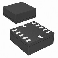
BMA020 Bosch Sensortec, BMA020 Datasheet - Page 21

BMA020
Manufacturer Part Number
BMA020
Description
3-AXIS ACCELEROMETER DIGITAL I/F
Manufacturer
Bosch Sensortec
Datasheet
1.BMA020.pdf
(50 pages)
Specifications of BMA020
Axis
X, Y, Z
Acceleration Range
± 2g, 4g, 8g
Sensitivity
256LSB/g, 128LSB/g, 64LSB/g
Voltage - Supply
2 V ~ 3.6 V
Output Type
Digital
Bandwidth
3kHz
Interface
I²C, SPI
Mounting Type
Surface Mount
Package / Case
12-LGA
For Use With
828-1014 - BMA020 TRIBOX DEMO BOARD W/USB828-1008 - BMA020 DAUGHTERCARD FOR DEV KIT
Lead Free Status / RoHS Status
Lead free / RoHS Compliant
Other names
828-1000-2
Available stocks
Company
Part Number
Manufacturer
Quantity
Price
Part Number:
BMA020
Manufacturer:
BOSCH/博世
Quantity:
20 000
3.5 Data registers
3.5.1 Acc_x, acc_y, acc_z
Acceleration values are stored in the following registers to be read out through serial interface.
acc_x (02h, 7-6; 03h, 7-0)
acc_y (04h, 7-6; 05h, 7-0)
acc_z (06h, 7-6; 07h, 7-0)
The description of the digital signals acc_x, acc_y and acc_z is “2’s complement”.
From negative to positive accelerations, the following sequence for the ±2g measurement range
can be observed (±4g and ±8g correspondingly):
-2.000g
-1.996g
...
-0.004g
+0.004g
...
+1.992g
+1.996g
Data is periodically updated (rate 3kHz) with values from the digital filter output. LSB
acceleration bytes must be read first. After an acceleration LSB byte read access, the
corresponding MSB byte update can optionally be blocked until it is also accessed for read.
Thus, MSB / LSB mix from different samples can be avoided (section 3.1.6).
It is not possible to read-out only MSB bytes if shadow_dis=0, an LSB byte must first be read
out. To be able to read out only MSB byte, shadow_dis must be written to 1.
new_data_* flags on bits 0 of acc_x (LSB), acc_y (LSB) and acc_z (LSB) can be used to detect
if acceleration values have already been read out (section 3.5.3).
If systematic acceleration values read out is planned (for signal processing by the
microcontroller), the interrupt pad can be programmed to flag the new data (section 3.2.10).
Every time all three axes values have been updated, the interrupt goes high and microcontroller
can read out data. With this method, microcontroller accesses are synchronized with internal
sensor IC updates.
Synchronization of read-out sequence has several advantages:
Rev. 1.2
© Bosch Sensortec GmbH reserves all rights even in the event of industrial property rights. We reserve all rights of disposal such
as copying and passing on to third parties. BOSCH and the symbol are registered trademarks of Robert Bosch GmbH, Germany.
Note: Specifications within this document are subject to change without notice.
0.000g
−
−
−
it enables a constant phase shift between acceleration conversion and its corresponding
digital value read by microprocessor
it reduces interface communication by avoiding over-sampling.
potential noise due to serial interface activity perturbation would always be generated
during a less critical phase of the conversion cycle. The maximum delay advised to start
read out acceleration data is 20µs after INT high (window 0-80µs).
:
:
:
:
:
:
10 0000 0000
10 0000 0001
11 1111 1111
:00 0000 0000
00 0000 0001
01 1111 1110
01 1111 1111
Digital, triaxial acceleration sensor
Data sheet
BMA020
Page 21
Bosch Sensortec
30 May 2008


