093.20 FINDER, 093.20 Datasheet

JUMPER LINK, 20WAY

093.20

Manufacturer Part Number
093.20
Description
JUMPER LINK, 20WAY
Manufacturer
FINDER
Series
93r
Datasheets

Specifications of 093.20

Accessory Type
Jumper
No. Of Positions
20
Pitch Spacing
6.2mm
Svhc
No SVHC (15-Dec-2010)
Colour
Blue
Connector Type
Jumper (Busbar)
Current Rating
36A
Rohs Compliant
YES
For Use With
38 Series Relay Interface Modules
Lead Free Status / RoHS Status
Lead free / RoHS Compliant
1 Pole - 6 A electromechanical relay
interface modules, 6.2 mm wide.
Ideal interface for PLC and electronic systems
Features
Contact specification
Contact configuration
Rated current/Maximum peak current
Rated voltage/Maximum switching voltage V AC
Rated load AC1
Rated load AC15 (230 V AC)
Single phase motor rating (230 V AC)
Breaking capacity DC1: 30/110/220 V
Minimum switching load
Standard contact material
Coil specification
Nominal voltage (U
Rated power AC/DC
Operating range
Holding voltage
Must drop-out voltage
Technical data
Mechanical life
Electrical life at rated load AC1
Operate/release time
Insulation between coil and contacts (1.2/50 µs)
Dielectric strength between open contacts
Ambient temperature range (≤ 60 V/>60 V) °C
Protection category
Approvals relay (according to type)
Sensitive DC coil or AC/DC coil versions
Integral coil indication and protection circuit
Instant ejection of relay using plastic
retaining clip
UL Listed
35 mm rail (EN 50022) mounting
38.51
38.61
6.2
6.2
220-240
V~
12
11
14
A1
A2
N
)
75.6
75.6
VA (50 Hz)/W
mW (V/mA)
V AC/DC
AC/DC
AC/DC
AC/DC
cycles
cycles
V DC
V AC
kW
DC
VA
VA
ms
kV
A
A
Screw terminal
1 pole electromechanical relay
35 mm rail mounting
A1
38 Series - Relay interface modules 0.1 - 2 - 6 - 8 A
A2
–40…+70/–40...+55
0.1 U
0.6 U
protection
indication
see page 121
(0.8...1.1)U
(0.8...1.2)U
500 (12/10)
1 CO (SPDT)
12 - 24 - 48 - 60 - (110…125) - (220…240)
6/0.2/0.15
circuit
250/400
and
6 (8 mm)
10 · 10
60 · 10
38.51
N
1,500
0.185
1,000
6/10
AgNi
N
IP 20
300
5/6
/ 0.05 U
/ 0.6 U
6 - 12 - 24 - 48 - 60 (non polarized)
6
3
N
N
N
N
14
11
12
Screwless terminal
1 pole electromechanical relay
35 mm rail mounting
A1
A2
–40…+70/–40...+55
0.1 U
0.6 U
see page 121
protection
indication
(0.8...1.1)U
(0.8...1.2)U
500 (12/10)
1 CO (SPDT)
6/0.2/0.15
circuit
250/400
6 (8 mm)
and
10 · 10
60 · 10
38.61
N
1,500
0.185
1,000
6/10
AgNi
N
IP 20
300
5/6
/ 0.05 U
/ 0.6 U
6
3
N
N
N
N
14
11
12
(94...138)U
Leakage current suppression
1 pole electromechanical relay
35 mm rail mounting
A1
A2
(110…125)
38.51.3 / 38.61.3
44 V
1/1
suppression
0.6 U
—/–40...+55
500 (12/10)
1 CO (SPDT)
leakage
6/0.2/0.15
current
circuit
250/400
6 (8 mm)
10 · 10
60 · 10
1,500
0.185
1,000
6/10
N
AgNi
IP 20
N
300
5/6
/ 0.6 U
(230…240)AC only
(184...264)U
6
3
0.5/—
92 V
N
12
14
11
115
N
38

Related parts for 093.20

093.20 Summary of contents

Page 1

Features 1 Pole - 6 A electromechanical relay interface modules, 6.2 mm wide. Ideal interface for PLC and electronic systems Sensitive DC coil or AC/DC coil versions • Integral coil indication and protection circuit • Instant ejection of relay using ...

Page 2

Features 2 Pole - 8 A electromechanical relay interface modules wide. Ideal interface for PLC and electronic systems Sensitive DC coil versions • Integral coil indication and protection circuit • Instant ejection of relay using plastic retaining clip ...

Page 3

Features Single output - solid state relay interface modules, 6.2 mm wide Ideal interface for PLC and electronic systems DC AC/DC input versions • Supplied with integral coil indication and • protection circuit Silent, high switching speed and ...

Page 4

Ordering information Electromechanical relay 1 Pole Example: 38 series relay interface module (SPDT coil Series Type 5 = Electromechanical relay, with screw terminal 6 = Electromechanical relay, with screwless terminal ...

Page 5

Ordering information Solid state relay Example: 38 series SSR relay interface module supply Series Type 8 = SSR relay, with screw terminal 9 = SSR relay, with screwless terminal ...

Page 6

Technical data Insulation Insulation according to EN 61810-1 ed. 2 Insulation between coil and contacts (1.2/50 µs) Dielectric strength between open contacts Conducted disturbance immunity Burst (5...50)ns, 5 kHz Surge (1.2/50 µ ...

Page 7

Coil specifications Coil data AC/DC, 1 Pole Nominal Coil Operating range voltage code min max 0.012 9.8 13.2 0.024 24 19.2 26.4 48 0.048 38.4 52.8 60 0.060 48 66 0.125 110…125 ...

Page 8

Technical data Other data Power lost to the environment without output current with rated current Wire strip length Screw torque Max. wire size Input specification Input data - AC/DC Nominal Supply Operating range voltage code min ...

Page 9

Combination for Electromechanical Relay Screw terminal - 1 Pole relay Code 38.51.0.012.0060 38.51.0.024.0060 38.51.0.048.0060 93.01 38.51.0.060.0060 38.51.0.125.0060 38.51.0.240.0060 38.51.3.125.0060 38.51.3.240.0060 38.51.7.006.0050 93.51 38.51.7.012.0050 38.51.7.024.0050 38.51.7.048.0050 38.51.7.060.0050 Screwless terminal - 1 Pole relay Code 93.02 38.61.0.012.0060 38.61.0.024.0060 38.61.0.125.0060 38.61.0.240.0060 38.61.3.125.0060 38.61.3.240.0060 ...

Page 10

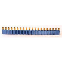
... Sheet of marker tags for 38.x2, plastic, 72 tags, 6x12 mm 060.72 060.72 124 38 Series - Relay interface modules 0 121.5 2.8 6.2 6.2 6.2 6.2 6.2 6.2 6.2 6.2 1. 12.7 0.8 1 2.85 7.2 6.8 7.2 6.8 7.2 6.8 7.2 6.8 10.5 093. 250 V 093. 250 V 093.01 ...

Related keywords