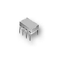
NTE890 NTE ELECTRONICS, NTE890 Datasheet

NTE890
Manufacturer Part Number
NTE890
Description
IC, V/F CONVERTER, 8-DIP
Manufacturer
NTE ELECTRONICS
Datasheet
1.NTE890.pdf
(2 pages)
Specifications of NTE890
Supply Voltage Range
8V To 22V
Digital Ic Case Style
DIP
No. Of Pins
8
Supply Voltage Max
22V
Operating Temperature Range
-20°C To +75°C
Supply Voltage Min
8V
Package / Case
8-DIP
Rohs Compliant
Yes
Input Voltage Primary Max
22V
Output Current Max
20mA
Lead Free Status / RoHS Status
Lead free / RoHS Compliant
Description:
The NTE890 is an integrated circuit in an 8–Lead DIP type package and provides a simple method
of A/D conversion. It has all the inherent advantages of the voltage–to–frequency conversion tech-
nique. The output is a series of constant duration pulses. The frequency of the pulses is proportional
to the applied input voltage. This converter is designed for use in a wide range of data conversion
and remote sensing applications.
Absolute Maximum Ratings: (T
Supply Voltage, V+
Output Sink Current, I
Power Dissipation, P
Input Voltage, V
Operating Temperature Range, T
Storage Temperature Range, T
Electrical Characteristics: (V+ = +15V, T
Note 1 Input Common Mode Range includes GND.
Supply Current
Conversion Accuracy Scale Factor
Drift with Temperature
Drift with V+
Input Comparator Offset Voltage
One–Shot Threshold Voltage
Offset Current
Input Bias Current
Common Mode Range
Input Bias Current
Reset V
SAT
Parameter
i
. . . . . . . . . . . . . . . . . . . . . . . . . . . . . . . . . . . . . . . . . . . . . . . . . . . . . . . . . .
. . . . . . . . . . . . . . . . . . . . . . . . . . . . . . . . . . . . . . . . . . . . . . . . . . . . . . . . . . . .
D
SINK
. . . . . . . . . . . . . . . . . . . . . . . . . . . . . . . . . . . . . . . . . . . . . . . . . . . . . . . . . .
Voltage to Frequency Converter
. . . . . . . . . . . . . . . . . . . . . . . . . . . . . . . . . . . . . . . . . . . . . . . . . . . . . . . . .
stg
opr
8V < V+ < 15V
15V < V+ < 22V
V
V
V
Note 1
Pin5
Pin5
Pin5, I = 2.2mA
A
IN
IN
IN
. . . . . . . . . . . . . . . . . . . . . . . . . . . . . . . . . . . . . . . . . .
= +25 C unless otherwise specified)
Integrated Circuit
= 10V, R
= 10V
= 1V, 8V < V+ < 18V
. . . . . . . . . . . . . . . . . . . . . . . . . . . . . . . . . . . . . . . . .
Test Conditions
A
NTE890
S
= +25 C unless otherwise specified)
= 14k
0 to V+ –3 0 to V+ –2
0.63
Min
2.0
2.0
0.9
–
–
–
–
–
–
–
–100
–100
0.66
0.15
Typ
3.5
4.5
1.0
0.2
100
5
50
–40 to +125 C
–300
–500
Max
0.70
0.50
–0.2V to V+(V)
6.0
7.5
1.1
1.0
10
100
–20 to +75 C
–
–
8V to 22V
500mW
ppM/ C
kHz/V
x V+
Unit
%/V
20mA
mA
mV
mA
nA
nA
nA
V
V
Related parts for NTE890
NTE890 Summary of contents
Page 1
... Voltage to Frequency Converter Description: The NTE890 is an integrated circuit in an 8–Lead DIP type package and provides a simple method of A/D conversion. It has all the inherent advantages of the voltage–to–frequency conversion tech- nique. The output is a series of constant duration pulses. The frequency of the pulses is proportional to the applied input voltage ...
Page 2
Electrical Characteristics (Cont’d): (V+ = +15V, T Parameter Current Source Output Current Change with Voltage Off Leakage Reference Voltage Logic Output V SAT V SAT Off Leakage Note 2. The voltage applied to comparator input Pin6 and Pin7 should not ...


