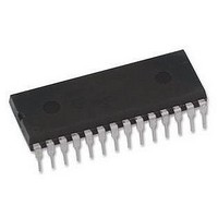
USB-SPI-DIL HEXWAX, USB-SPI-DIL Datasheet - Page 6

USB-SPI-DIL
Manufacturer Part Number
USB-SPI-DIL
Description
IC, BRIDGE, USB-SERIAL SPI, DIL28
Manufacturer
HEXWAX
Datasheet
1.USB-SPI-DIL.pdf
(9 pages)
Specifications of USB-SPI-DIL
Digital Ic Case Style
DIP
No. Of Pins
28
Package / Case
DIL
Termination Type
Through Hole
Supply Voltage Range
2.7V To 5.5V
Rohs Compliant
Yes
Lead Free Status / RoHS Status
Lead free / RoHS Compliant
should be monitored if the device can draw more than
100mA.
Power considerations
Initially, the device will request the full power it is
configured for. If it is not granted this power level within
three seconds, it performs a soft detach and requests a
maximum of 100mA. This allows devices to operate in a
low power mode when connected to an unpowered hub.
This reduced power mode is indicated by the Low Pwr
Indication pin.
If the device is electromagnetically noisy, a ferrite bead
is recommended on the USB Vdd supply in order to
suppress any transmission of noise to the rest of the
USB network. 100nF smoothing capacitors should be
provided on all independently switched power rails to
avoid momentary brown-out conditions.
When designing self powered circuits, ensure power can
never be fed into the Vdd USB line.
AN1149 from Microchip Technology, in the development
kit, discusses designs for recharging batteries using
USB bus power.
USB Connectors
Common USB connector and cable configurations are
shown in figure 6 and table 6.
connector should be left unconnected. The ID pin on
the mini connector permits the distinction of A and B
plugs. The micro connector pin-out is the same as the
mini connector.
For ultra-low cost products, it is possible to form a USB
Type-A plug direct from a circuit board as shown in
figure 7. This connector is only suitable for a number of
insertions (~50 before cleaning is required).
unshielded and recommended only for ‘dongle’ type
products with no cables attached.
p6 of 9
Std Mini
1
2
3
–
4
Pin
1
2
3
4
5
Figure 6 Common USB pin-outs for male connectors
Name
Gnd
Vcc
D–
D+
Vdd
ID
Table 6. USB Connection Key
Cable
Green
White
color
Black
Red
–
R1
C4
AllSysGo
26-Aug-10
T1
R6
Description
+5V (can dip to 4.08V)
Data –
Data +
Type A: Connect to ground
Type B: Not connected
Signal ground
Vout
The shield on the
Figure 5
Design note
USB-SPI
It is
For further dimensional information, refer to figure 6-7 of
the USB 2.0 Specification, in the development kit.
Host-Side Interfacing
USB-SPI uses the Human Interface Device (HID) USB
interface. It has the advantages that no device drivers
are required, and that a host application can easily
locate the USB-SPI.
All exchanges of data (‘reports’) between the host and
the USB-SPI are 64 bytes in length, regardless of how
many bytes of meaningful data are actually transferred.
In HID terms, all transfers are 1ms interrupt reports of
64 bytes, to and from output ID 0 on EP1.
The host software has two perform two tasks. First it
has to locate the device. Then it has to communicate
with it. To locate the device, enumerate all devices with
Vendor ID 0x0B40 and Product ID 0x011C (28-pin
devices) or 0x012B (20-pin devices). Then use a Get
Feature request for the string 4, the Product GUID. If
this matches the product GUID you configured for the
device, you have located it.
Once you have located the device, you need to open a
file to communicate with it. You can then send data and
receive data as 64-byte reports.
Sample source code for Windows and a Windows
dynamic link library (DLL) are provided in the
development kit. For a detailed description, please refer
to the comments embedded in the source code and the
Visual Basic example in the Excel spreadsheet. Sample
source code for Mac OS and Linux is in preparation.
Sending and Receiving Data
The first byte of the report (byte 0) is termed the
identifier. If its value is 0x01-0x3F, then it indicates that
the packet is data for transmission to or received from
the TxD and RxD pins. The value equals the number of
data bytes being transferred. The data is located from
byte 1 of the report onwards.
If its value is 0x41-0x7F, it should be interpreted exactly
the same as 0x01-0x3F except the value equals the
number of data bytes being transferred plus 0x40, and
the report must be acknowledged before the next data
report is sent.
sending a report with an identifier of value 0x40.
Prior to writing your own software, you can use the
12.00
HIDconfig.exe software in the development kit to
evaluate USB-SPI.
0.50
3.00
1.00-2.00
Shoulder required to prevent over-insertion
1.00
1.00
HW144-7
Overall PCB width 16.00 or less
2.25
1.25
A data report is acknowledged by
11.75
4. Vss
3. D+
2. D-
1. Vdd
including tracks 2.00 - 2.20
Contacts plated with hard
gold flash (0.25-1.27µm)
over nickel (2.6-5.0µm)
Overall PCB thickness
www.hexwax.com
Dimensions in mm
Figure 7


