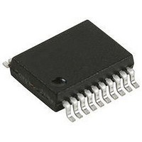
USB-SPI-SS HEXWAX, USB-SPI-SS Datasheet - Page 7

USB-SPI-SS
Manufacturer Part Number
USB-SPI-SS
Description
IC, USB TO SERIAL SPI INTERFACE, SSOP-20
Manufacturer
HEXWAX
Datasheet
1.USB-SPI-DIL.pdf
(9 pages)
Specifications of USB-SPI-SS
Supply Voltage Range
1.8V To 5V
Digital Ic Case Style
SSOP
No. Of Pins
20
Termination Type
SMD
Package / Case
20-SSOP
Filter Terminals
SMD
Rohs Compliant
Yes
Lead Free Status / RoHS Status
Lead free / RoHS Compliant
(Note: Prior to rev 0007, the maximum number of data
bytes is 0x3E, i.e. the identifiers 0x3F and 7F are not
permitted.)
Commands
All commands are sent using identifiers of value 0x80 or
higher. If a response to the command is required, the
response will have the same identifier as the command
to which it is responding. The Interrupt response has no
command associated with it and it may be received by
the host at any time.
Note: Accidentally sending a command in the range
0x80-0x8F can modify settings that may permanently
disable the device. During product development, it is
recommended that you work with a device that has been
write locked using HIDconfig.exe. Devices intended for
production should always be write locked.
Get Pin
The identifier GETPIN (0x90) retrieves value of a pin.
The command payload has one byte, which indicates
the pin, as shown in table 7. The response payload has
two bytes, as shown in table 7.
Example:
Get Analog
The identifier GETANALOG (0x96) retrieves the voltage
of the analog pin. The command has not payload. The
response payload has two bytes, representing a number
from 0x0000 to 0x03FF, which indicates the voltage
relative to Vdd.
Example:
Set Pin
The identifier SETPIN (0x91) sets the value of any
output pin. The command payload has two bytes, which
indicate the pin and the desired output.
Example:
p7 of 9
90 25
90 25 01
96
96 02 36
91 25 01
HostRdy
USBPwr
SelfPwr
Send
VIO10
VIO0
VIO1
VIO2
VIO3
VIO4
VIO5
VIO6
VIO7
VIO8
VIO9
Pin
Table 7. Get Pin / Set Pin Payload Structure*
†
Payload byte 1
Command – Get DTR pin
Response – Pin is active
Command – Get Analog
Response – V = Vdd * (0x236/0x3FF)
Command – Set DTR pin active
0x1A
0x10
0x11
0x12
0x13
0x14
0x15
0x16
0x17
0x18
0x19
0x20
0x21
0x26
0x27
26-Aug-10
00 = Inactive, 01 = Active
00 = Inactive, 01 = Active
00 = Inactive, 01 = Active
00 = Inactive, 01 = Active
00 = Low, 01 = High
00 = Low, 01 = High
00 = Low, 01 = High
00 = Low, 01 = High
00 = Low, 01 = High
00 = Low, 01 = High
00 = Low, 01 = High
00 = Low, 01 = High
00 = Low, 01 = High
00 = Low, 01 = High
00 = Low, 01 = High
Payload byte 2**
USB-SPI
Host Ready
The Host Ready feature is used to indicate to the device
that a host application is running, has located the device,
and is ready to communicate with it.
If the Host Ready pin is implemented, the application
should tell the device when it is ready using the Host
Ready command.
HOSTREADY (0x92) and one payload byte, which is
0x01 if the application is initialized and available, or
0x00 if the application is shutting down and not longer
available.
Interrupt
The Interrupt response is an unprompted message from
the device that an interrupt input transitioned from the
inactive to the active state.
It consists of the identifier INTERRUPT (0x95) and one
payload byte, which is 0x09 if the interrupt occurred on
pin VIO9.
Set Serial
The identifier SETSERIAL (0x93) temporarily sets the
mode of operation of the SPI port. These settings are
not remembered after device reset and should be used
if the settings are to be adjusted under software control.
The command payload has 4 bytes as shown in table 8.
Example:
Get Firmware ID
The identifier GETFWID (0x94) retrieves a zero-
terminated ASCII text string identifying the firmware and
its version number.
Byte
RxBuffNotFull
TxBuffEmpty
92 03 00 02 FF FF
0
1
2
3
4
LowPower
AllSysGo
Suspend
TxRxInd
Config
RxInd
SS#
TxInd
Pin
NullRxCh
NullTxCh
Identifier
Table 7. Get Pin / Set Pin Payload Structure*
Name
Mode
Flags
†
HW144-7
†
†
** Used in Get Pin Response and Set Pin Command only
*Byte 0 is the identifier 0x90 (Get Pin) or 0x91 *Set Pin)
Payload byte 1
Description / Value
0x92
Bit 0 set for data Acknowledged
Bit 1 set if NullRxCh is to be ignored
Null Tx character
Null Rx character
Table 8. Set Serial
0x00 = “D”, “0”, “0,0
0x01 = “B”, “1”, “0,0
0x02 = “C”, “2”, “1,0
0x03 = “A”, “3”, “1,1
(See table 3.)
0x2A
0x2B
0x2C
0x2D
0x2E
0x28
0x29
0x30
0x34
0x32
It consists
Command – Set mode A, no
ack, Null Tx and Rx is 0xFF
00 = Inactive, 01 = Active
00 = Inactive, 01 = Active
00 = Inactive, 01 = Active
00 = Inactive, 01 = Active
00 = Inactive, 01 = Active
00 = Inactive, 01 = Active
00 = Inactive, 01 = Active
00 = Inactive, 01 = Active
00 = Inactive, 01 = Active
00 = Inactive, 01 = Active
Payload byte 2**
of the identifier
www.hexwax.com
† Not settable


