LM2590HVT-5.0 National Semiconductor, LM2590HVT-5.0 Datasheet
LM2590HVT-5.0
Specifications of LM2590HVT-5.0


Related parts for LM2590HVT-5.0

LM2590HVT-5.0 Summary of contents
Page 1
... Typical Application (Fixed Output Voltage Versions) SIMPLE SWITCHER ® and Switchers Made Simple ® are registered trademarks of National Semiconductor Corporation. © 2001 National Semiconductor Corporation Power Converter 150 kHz 1A ® Features n 3.3V, 5V, and adjustable output versions n Adjustable version output voltage range, 1.2V to 57V ± ...
Page 2
... Absolute Maximum Ratings If Military/Aerospace specified devices are required, please contact the National Semiconductor Sales Office/ Distributors for availability and specifications. Maximum Supply Voltage ( /SS Pin Input Voltage (Note 2) Delay Pin Voltage (Note 2) Flag Pin Voltage Feedback Pin Voltage Output Voltage to Ground (Steady State) ...
Page 3
LM2590HV-ADJ Electrical Characteristics Specifications with standard type face are for T ture Range. Symbol Parameter Efficiency V = 12V All Output Voltage Versions Electrical Characteristics Specifications with standard type face are for T ture Range. Unless otherwise specified, ...
Page 4
All Output Voltage Versions Electrical Characteristics Specifications with standard type face are for T ture Range. Unless otherwise specified, V Symbol Parameter FLAG/DELAY CONTROL Test Circuit of Figure 1 Regulator Dropout Detector Threshold Voltage VF Flag Output Saturation SAT Voltage ...
Page 5
Typical Performance Characteristics NormalizedOutput Voltage 10134702 Switch SaturationVoltage 10134705 Operating Quiescent Current 10134708 (Circuit of Figure 1 ) Line Regulation 10134703 Switch Current Limit 10134706 Shutdown Quiescent Current 10134709 5 Efficiency 10134704 Dropout Voltage 10134707 Minimum Operating Supply Voltage 10134710 ...
Page 6
Typical Performance Characteristics Feedback Pin Bias Current 10134711 Soft-start 10134714 Soft-start Response 10134718 www.national.com (Circuit of Figure 1 ) (Continued) Flag Saturation Voltage 10134712 Shutdown /Soft-start Current 10134715 Shutdown/Soft-start Threshold Voltage Internal Gain-Phase Characteristics 10134753 6 Switching Frequency 10134713 Delay ...
Page 7
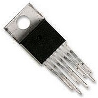
... Horizontal Time Base: 50 µs/div. A: Output Voltage, 100 mV/div. (AC) B: 250 Load Pulse Connection Diagrams and Order Information Bent and Staggered Leads, Through Hole Package 7-Lead TO-220 (T) Order Number LM2590HVT-3.3, LM2590HVT-5.0, or LM2590HVT-ADJ See NS Package Number TA07B (Circuit of Figure 1 ) (Continued) Discontinuous Mode Switching Waveforms = 1A ...
Page 8
Test Circuit and Layout Guidelines Component Values shown are for V = 15V 5V 1A. OUT LOAD C — 470 µF, 50V, Aluminum Electrolytic Nichicon “PM Series” — 220 µF, 25V Aluminum Electrolytic, ...
Page 9
Block Diagram PIN FUNCTIONS +V (Pin 1) — This is the positive input supply for the IC IN switching regulator. A suitable input bypass capacitor must be present at this pin to minimize voltage transients and to supply the switching ...
Page 10
PIN FUNCTIONS (Continued) Note If any of the above three features (Shutdown /Soft-start, Error Flag, or Delay) are not used, the respective pins can be left open. www.national.com FIGURE 2. Soft-Start, Delay, Error Output 10 10134731 ...
Page 11
INDUCTOR VALUE SELECTION GUIDES (For Continuous Mode Operation) FIGURE 3. Timing Diagram for 5V Output FIGURE 4. LM2590HV-3.3 11 10134732 10134726 www.national.com ...
Page 12
INDUCTOR VALUE SELECTION GUIDES www.national.com (For Continuous Mode Operation) (Continued) FIGURE 5. LM2590HV-5.0 FIGURE 6. LM2590HV-ADJ 12 10134727 10134729 ...
Page 13
INDUCTOR VALUE SELECTION GUIDES Coilcraft Inc. Coilcraft Inc., Europe Pulse Engineering Inc. Pulse Engineering Inc., Europe Renco Electronics Inc. Schott Corp. Cooper Electronic Tech. (Coiltronics) FIGURE 8. Contact Information for Suggested Inductor Manufacturers (For Continuous Mode Operation) (Continued) FIGURE 7. ...
Page 14
Application Information INDUCTOR SELECTION PROCEDURE Application Note AN-1197 titled ’Selecting Inductors for Buck Converters’ provides detailed information on this topic. For a quick-start the designer may refer to the nomographs pro- vided in Figure 4 to Figure ...
Page 15
Application Information Therefore, looking at Figure 4 we quick-select a 100µH/1A inductor (designed for 150 kHz operation) for this applica- tion should confirm that it is rated to handle 100 µJ (see Figure the procedure ...
Page 16
Application Information FIGURE 9. Typical Circuit Using Shutdown /Soft-start and Error Flag Features FIGURE 10. Inverting −5V Regulator With Shutdown and Soft-start lNVERTING REGULATOR The circuit in Figure 10 converts a positive input voltage to a negative output voltage with ...
Page 17
Application Information suming 100% efficiency, which is never so. Therefore expect additional 10-20% higher than calculated from PEAK the above equation. The reader is also referred to Application Note AN-1157 for examples based on positive to ...
Page 18
Application Information possible. For best results, external components should be located as close to the switcher lC as possible using ground plane construction or single point grounding. If open core inductors are used, special care must be taken as to ...
Page 19
... Physical Dimensions inches (millimeters) unless otherwise noted Order Number LM2590HVT-3.3, LM2590HVT-5.0 or LM2590HVT-ADJ 7-Lead TO-220 Bent and Staggered Package NS Package Number TA07B 19 www.national.com ...
Page 20
... NATIONAL’S PRODUCTS ARE NOT AUTHORIZED FOR USE AS CRITICAL COMPONENTS IN LIFE SUPPORT DEVICES OR SYSTEMS WITHOUT THE EXPRESS WRITTEN APPROVAL OF THE PRESIDENT AND GENERAL COUNSEL OF NATIONAL SEMICONDUCTOR CORPORATION. As used herein: 1. Life support devices or systems are devices or systems which, (a) are intended for surgical implant ...