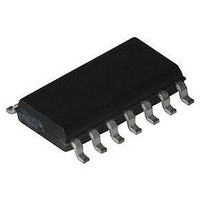
HFA3600IB Intersil, HFA3600IB Datasheet

HFA3600IB
Specifications of HFA3600IB
Related parts for HFA3600IB
HFA3600IB Summary of contents
Page 1
... S-parameters, noise figure, third-order intercept characterization data and PC board artwork. Evaluation boards are also available through local Intersil Sales offices. Part Number Information PART TEMP. o NUMBER RANGE ( C) PACKAGE HFA3600IB - SOIC Pinout HFA3600 (SOIC) TOP VIEW LNA GND 2 13 ...
Page 2
Absolute Maximum Ratings Supply Voltage . . . . . . . . . . . . . . . . . . . . . . . . . . . . . . . -0.3 to +6.0V Voltage ...
Page 3
AC Electrical Specifications All Characterization Results have been Obtained with the Use of a Standard Evaluation Board. (Continued) SYMBOL PARAMETER o MIXER ( 825MHz at -3dBm MIXER ...
Page 4
Test Circuits (Continued) DUPLEXER LNA IN 1000pF 1000pF FROM TRANSMITTER LO IN TABLE 1. TYPICAL CELLULAR FRONT-END CASCADED PERFORMANCE DUPLEXER Noise Figure 3.0 Gain -3.0 OUTPUT IP3 100.0 Cascaded Noise Figure = 8.55dB NOTE: Cascaded results are using 100.0dBm for ...
Page 5
LNA Characteristics 20 2dB/DIV 0 800 900 FREQUENCY (MHz) FIGURE 5. LNA S21 vs FREQUENCY AND V 0 2dB/DIV -20 800 900 FREQUENCY (MHz) FIGURE 7. LNA S11 vs FREQUENCY AND TEMPERATURE 0 2dB/DIV -20 800 900 FREQUENCY (MHz) FIGURE ...
Page 6
LNA Characteristics (Continued) 1 900MHz 0.0 -1.0 -2.0 -3.0 -4 TEMPERATURE ( FIGURE 11. LNA OUTPUT 1DB COMPRESSION vs TEMPERATURE 2.9 2.7 2.5 2.3 2 TEMPERATURE ...
Page 7
Mixer Characteristics 8.0 7.0 6.0 5 DRIVE (dBm) FIGURE 17. MIXER DRIVE 14.0 13.0 12.0 11 DRIVE (dBm) FIGURE 19. MIXER NF vs ...
Page 8
Mixer Characteristics (Continued) - 5.0 - 6.0 - 7.0 - 8.0 - 9 DRIVE (dBm) FIGURE 23. MIXER 1dB COMPRESSION vs LO DRIVE 4.0 3.0 2.0 1 ...
Page 9
Isolation Characteristics 0 10dB/DIV 85 25 -40 -100 700 850 FREQUENCY (MHz) FIGURE 29. LNA OUT TO MIXER RF ISOLATION vs FREQUENCY AND TEMPERATURE FIGURE 31. MIXER ISOLATION vs FREQUENCY AND TEMPERATURE 9 HFA3600 0 -100 1000 ...
Page 10
LNA Noise and Gain Characteristics 1 0.5 900MHz 1 2 FIGURE 32. LNA GAMMA OPTIMUM vs FREQUENCY 0 10 HFA3600 4.0 3 1.0 10 100MHz 600 5 FIGURE 33. MINIMUM NOISE FIGURE AND ASSOCIATED 1 0.5 ...
Page 11
Evaluation Board Layout Information Component List: R1 Res, fixed 1k L1 Ind., fixed Ind., fixed 390nH C3, C4, C5, C7, C10, C11 Cap, fixed 1nF NOTE: See Evaluation Board testing information. 11 HFA3600 C1, C6 Cap, fixed.01 ...
Page 12
... IF output from the MIXER. Device Description The HFA3600 is fabricated in the INTERSIL UHF-1 Bonded wafer, Silicon on Insulator process. ft characteristics of 10GHz and Power bandwidth product of 6GHz together with the robustness of the SOI process ensure high reliability for high frequency volume production ...
Page 13
The open collector output permits direct interface to moderate impedance IF filters as well as 50W input filters after a simple “L” impedance matching network. A collector resistor of 1K has been ...
Page 14
Evaluation Board Testing Information The following paragraphs contain information related to the evaluation of the HFA3600 LNA/Mixer noise figure and common errors encountered during individual and cascaded performance verification. A simple cascaded arrangement using a simple network as an intermediate ...
Page 15
FILTER BROADBAND FILTER A NOISE SOURCE HP346B LNA HFA3600 TUNED AT THE RF FREQ FIGURE 37A. SSB NOISE FIGURE MEASUREMENT FILTER BROADBAND NOISE SOURCE HP346B LNA HFA3600 FIGURE 37B. DSB NOISE FIGURE MEASUREMENT TABLE 3. DSB MEASUREMENT SET UP (NO ...
Page 16
... Accordingly, the reader is cautioned to verify that data sheets are current before placing orders. Information furnished by Intersil is believed to be accurate and reliable. However, no responsibility is assumed by Intersil or its subsidiaries for its use; nor for any infringements of patents or other rights of third parties which may result from its use ...


