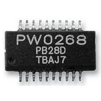
PW0268 PROWAVE, PW0268 Datasheet

PW0268
Specifications of PW0268
Related parts for PW0268
PW0268 Summary of contents
Page 1
... An adjustable System Clock: enables the control of, the number of pulses transmitted, the slope of the variable gain amplifier, and the pulse repetition rate. The PW0268 IC is suitable for use in car reversing aids, electronic tape measures and other sonar ranging applications. 1 ...
Page 2
... System Clock Timer High-Speed Comparator LP_O LP_I TCG_O Pro-Wave Electronics Corp. Tel: 886-2-22465101 Fax: 886-2-22465105 E-mail: sales@pro-wave.com.tw URL: http://www.prowave.com.tw ORC3 ORC2 ORC1 Ultrasonic R/C Oscillator Auto Frequency Tracking 32 Steps Fixed Gain TCG Amp Amp TCG_I GR_O 20 Vref 19 Vcc 18 Vreg 17 GND ...
Page 3
... Driver_O I_OVIH I_OVIL I_OVOH I_OVOL I_OIOL Rup Symbol Condition Vcc Topr Tstg I_O,Vcc Vimax Others Iimax 3 Pro-Wave Electronics Corp. Tel: 886-2-22465101 Fax: 886-2-22465105 E-mail: sales@pro-wave.com.tw URL: http://www.prowave.com.tw Min. Typ. Max. 5 3.8 4 -3.0 0 +3.0 0.4 0. 300 350 610 660 0.001 ...
Page 4
... Description Pin Vcc Vreg 47K 22p R1 100u 660KHZ PW0268 2200p 4.7K 2.7K 680p 680p 13K 4.7K 470p Vref Vref 4 Pro-Wave Electronics Corp. Tel: 886-2-22465101 Fax: 886-2-22465105 E-mail: sales@pro-wave.com.tw URL: http://www.prowave.com.tw Name Description Driver_O Transducer driving output Ftrace Frequency tracing input ...
Page 5
... Output at Pin 1 I_O: H: 1ms/Div., V: 5.0V/Div. Pro-Wave Electronics Corp. Tel: 886-2-22465101 Fax: 886-2-22465105 E-mail: sales@pro-wave.com.tw URL: http://www.prowave.com.tw The RC oscillator will be enabled in the duration of input pulse. The maximum pulse width is 396/F and any time longer than this upper limit will be ignored. The next input pulse will be ignored if the pulse repetition rate is shorter than 9900/F + pulse width ...
Page 6
... For additional information about an 18-meter tape measure circuit, please consult with the factory. R1(Ohm) R2(Ohm) 3,300 1,500 3,300 1,500 2,000 0 6 Pro-Wave Electronics Corp. Tel: 886-2-22465101 Fax: 886-2-22465105 E-mail: sales@pro-wave.com.tw URL: http://www.prowave.com.tw R3(Ohm) C1(pF) 511 2,200 604 2,200 2,100 220 ...
Page 7
... Time Controlled Gain Amplifier The time controlled gain amplifier is stepping up once the input pulse falling. The time duration can be calculated as 220 Steps F: Frequency of System Clock 7 Pro-Wave Electronics Corp. Tel: 886-2-22465101 Fax: 886-2-22465105 E-mail: sales@pro-wave.com.tw URL: http://www.prowave.com. ...
Page 8
... Package and Dimensions: 20 Pins, SSOP (150mil) Pro-Wave Electronics Corp. Tel: 886-2-22465101 Fax: 886-2-22465105 E-mail: sales@pro-wave.com.tw URL: http://www.prowave.com.tw 8 ...
Page 9
... Pro-Wave Electronics Corp. Tel: 886-2-22465101 Fax: 886-2-22465105 E-mail: sales@pro-wave.com.tw URL: http://www.prowave.com.tw 9 ...
Page 10
... R1 0.003 - θ - 0° θ1 - 5° θ2 - 0° aaa 0.004 bbb 0.008 ccc 0.004 ddd 0.007 eee 0.004 10 Pro-Wave Electronics Corp. Tel: 886-2-22465101 Fax: 886-2-22465105 E-mail: sales@pro-wave.com.tw URL: http://www.prowave.com.tw Max. 0.069 0.010 0.065 0.012 0.011 0.010 0.009 0.050 - - 8° 15° - ...
Page 11
... The dambar can not be located on the lower radius of the foot. 9. Refer to JEDEC MO-137 variation AD. JEDEC is the registered trademark of JEDEC SOLID STATE TECHNOLOGY ASSOCIATION Pro-Wave Electronics Corp. Tel: 886-2-22465101 Fax: 886-2-22465105 E-mail: sales@pro-wave.com.tw URL: http://www.prowave.com.tw Copyright © 2004 Pro-Wave Electronics Corp. 9/15/2004 11 ...
Page 12
... Bi-directional I/O Measuring distance SRM400 1. Module board 2. 400EP14D enclosed type transducer of asymmetrical beam patterns, see detail specification of 400EP14D. 3. Detail electrical schematic prowave@ms3.hinet.net; Tel: 886-2-22465101(5 lines), 22459774; Fax: 886-2-22465105 SRM400 DC6 - 10V <20 mA @DC10V max. Fc: 38 KHz Bandwidth: 20KHz Insertion loss 130Vpp ...
Page 13
... Point: Transducer loading “E” Point: Main 32 Steps TCG Amplifier Refer to PW-0268 Sonar Ranging IC Vcc Vreg 1K 47K 22p 3.3K 100u 660KHZ PW0268 2200p 4.7K 2.7K 680p 680p 13K 4.7K 470p Vref Vref “B” Point: H: 0.5ms/div V: 5V/div “D” Point ...
Page 14
... K4000001 K4000002 40.0 KHz 40.0 KHz 10.6 mH± 6% 10.6 mH± 100 1:10 1:10 400EP14D 400EP14D (Temperature Compensated Type prowave@ms3.hinet.net; Tel: 886-2-22465101(5 lines), 22459774;Fax: 886-2-22465105 Series Shunt Drive Resistance Capacitance Level Ohm pF 35,000 2.3 0.001 35,000 2.3 0.001 ...


