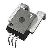
ACS756SCA-100B-PFF-T Allegro Microsystems Inc, ACS756SCA-100B-PFF-T Datasheet

ACS756SCA-100B-PFF-T
Specifications of ACS756SCA-100B-PFF-T
Available stocks
Related parts for ACS756SCA-100B-PFF-T
ACS756SCA-100B-PFF-T Summary of contents
Page 1
... RMS pins 1-3 to pins 4-5 ▪ 3.0 to 5.0 V, single supply operation ▪ 3 μs output rise time in response to step input current ▪ mV/A output sensitivity ▪ Output voltage proportional currents ▪ Factory-trimmed for accuracy ▪ Extremely stable output offset voltage ▪ ...
Page 2
... Selection Guide T OP Part Number 1 (°C) ACS756SCA-050B-PFF-T – ACS756SCA-100B-PFF-T – ACS756KCA-050B-PFF-T –40 to 125 1 Additional leadform options available for qualified volumes 2 Contact Allegro for additional packing options. Absolute Maximum Ratings Characteristic ...
Page 3
... ACS756 with 3 kVRMS Voltage Isolation and a Low-Resistance Current Conductor IP+ IP– Terminal List Table Number Fully Integrated, Hall Effect-Based Linear Current Sensor IC Functional Block Diagram VCC To all subcircuits Amp Temperature Gain Coefficient Trim Control GND Pin-out Diagram IP VIOUT 2 GND 1 VCC IP– ...
Page 4
... ACS756 with 3 kVRMS Voltage Isolation and a Low-Resistance Current Conductor COMMON OPERATING CHARACTERISTICS Characteristic Symbol Supply Voltage 2 V Supply Current I CC Power On Time t PO Rise Time t Internal Bandwidth 3 BW Output Load Resistance R LOAD(MIN) Output Load Capacitance C LOAD(MAX) Primary Conductor Resistance R PRIMARY Symmetry ...
Page 5
... Nonlinearity E LIN(LT) V OE(TA) Electrical Offset Voltage 3 V OE(TOP)HT V OE(TOP)LT E TOT(HT) Total Output Error 4 E TOT(LT) 1 Device may be operated at higher primary current levels (max), is not exceeded 6σ noise voltage drift is referred to ideal OE(TOP Percentage with Output filtered Fully Integrated, Hall Effect-Based Linear Current Sensor IC ...
Page 6
... Nonlinearity E LIN(LT) V OE(TA) 3 Electrical Offset Voltage V OE(TOP)HT V OE(TOP)LT E TOT(HT) 4 Total Output Error E TOT(LT) 1 Device may be operated at higher primary current levels (max), is not exceeded 6σ noise voltage drift is referred to ideal OE(TOP Percentage with Output filtered Fully Integrated, Hall Effect-Based Linear Current Sensor IC ...
Page 7
... E is divided into four areas: TOT 25°C. Accuracy at the zero current flow at 25°C, with- out the effects of temperature. IOUT(Q) over Δ temperature. Accuracy at the zero current flow ...
Page 8
... Propagation delay (t ). The time required for the device PROP output to reflect a change in the primary current signal. Propaga- tion delay is attributed to inductive loading within the linear IC package, as well as in the inductive loop formed by the primary conductor geometry. Propagation delay can be considered as a fixed time offset and may be compensated. ...
Page 9
... ACS756 with 3 kVRMS Voltage Isolation and a Low-Resistance Current Conductor Chopper Stabilization Technique Chopper Stabilization is an innovative circuit technique that is used to minimize the offset voltage of a Hall element and an asso- ciated on-chip amplifier. Allegro patented a Chopper Stabiliza- tion technique that nearly eliminates Hall IC output drift induced by temperature or package stress effects ...
Page 10
... ACS756 with 3 kVRMS Voltage Isolation and a Low-Resistance Current Conductor Package CA, 5-pin package, leadform PFF 14.0±0.2 3.0±0 13.00±0.10 4.40±0. 10.00±0.10 0.51±0.10 Fully Integrated, Hall Effect-Based Linear Current Sensor IC 1.50±0.10 4.0±0.2 1º±2° A 3.5±0.2 17.5± ...
Page 11
... ACS756 with 3 kVRMS Voltage Isolation and a Low-Resistance Current Conductor Revision History Revision Rev. 6 Copyright ©2006-2011, Allegro MicroSystems, Inc. The products described herein are protected by U.S. patents: 6,781,359; and 7,265,531. Allegro MicroSystems, Inc. reserves the right to make, from time to time, such de par tures from the detail spec tions as may be required to per- mit improvements in the per for mance, reliability, or manufacturability of its products ...


