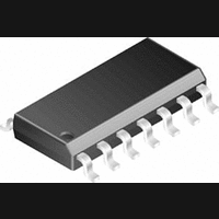
LM2574HVM-ADJ National Semiconductor, LM2574HVM-ADJ Datasheet - Page 16

LM2574HVM-ADJ
Manufacturer Part Number
LM2574HVM-ADJ
Description
DC/DC Converter IC
Manufacturer
National Semiconductor
Datasheet
1.LM2574HVM-ADJ.pdf
(24 pages)
Specifications of LM2574HVM-ADJ
Input Voltage
60V
Output Current
500mA
Output Voltage
57V
No. Of Pins
14
Peak Reflow Compatible (260 C)
No
Supply Voltage Max
60V
Leaded Process Compatible
No
Mounting Type
Surface Mount
Lead Free Status / RoHS Status
Contains lead / RoHS non-compliant
Available stocks
Company
Part Number
Manufacturer
Quantity
Price
Company:
Part Number:
LM2574HVM-ADJ
Manufacturer:
NS
Quantity:
1 210
www.national.com
LM2574 Series Buck Regulator Design Procedure
Application Hints
INPUT CAPACITOR (C
To maintain stability, the regulator input pin must be by-
passed with at least a 22 µF electrolytic capacitor. The ca-
pacitor’s leads must be kept short, and located near the
regulator.
If the operating temperature range includes temperatures
below −25˚C, the input capacitor value may need to be
larger. With most electrolytic capacitors, the capacitance
value decreases and the ESR increases with lower tempera-
tures and age. Paralleling a ceramic or solid tantalum ca-
pacitor will increase the regulator stability at cold tempera-
tures. For maximum capacitor operating lifetime, the
capacitor’s RMS ripple current rating should be greater than
IN
)
20V
30V
40V
50V
60V
90V
V
R
FIGURE 9. Diode Selection Guide
MBR120P
MBR130P
MBR140P
Schottky
10JQ030
MBR150
MBR160
11DQ03
11DQ04
11DQ05
11DQ06
11DQ09
1N5817
1N5818
1N5819
11JQ04
11JQ05
11JQ06
SR102
SR103
SR104
SR105
SR106
1 Amp Diodes
16
Fast Recovery
INDUCTOR SELECTION
All switching regulators have two basic modes of operation:
continuous and discontinuous. The difference between the
two types relates to the inductor current, whether it is flowing
continuously, or if it drops to zero for a period of time in the
normal switching cycle. Each mode has distinctively different
operating characteristics, which can affect the regulator per-
formance and requirements.
The LM2574 (or any of the Simple Switcher family) can be
used for both continuous and discontinuous modes of opera-
tion.
In many cases the preferred mode of operation is in the con-
tinuous mode. It offers better load regulation, lower peak
switch, inductor and diode currents, and can have lower out-
put ripple voltage. But it does require relatively large inductor
values to keep the inductor current flowing continuously, es-
pecially at low output load currents.
To simplify the inductor selection process, an inductor selec-
tion guide (nomograph) was designed (see Figure 4 through
Figure 8 ). This guide assumes continuous mode operation,
and selects an inductor that will allow a peak-to-peak induc-
tor ripple current ( I
maximum design load current. In the LM2574 SIMPLE
SWITCHER, the peak-to-peak inductor ripple current per-
centage (of load current) is allowed to change as different
design load currents are selected. By allowing the percent-
age of inductor ripple current to increase for lower current
applications, the inductor size and value can be kept rela-
tively low.
following
MUR110
HER102
rated to
diodes
11DF1
are all
10JF1
100V
The
(Continued)
IND
) to be a certain percentage of the


