C25BNF230B EATON CUTLER HAMMER, C25BNF230B Datasheet - Page 13
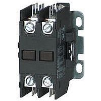
C25BNF230B
Manufacturer Part Number
C25BNF230B
Description
Definite Purpose Contactor
Manufacturer
EATON CUTLER HAMMER
Datasheet
1.C25FNF375A.pdf
(54 pages)
Specifications of C25BNF230B
Load Current Inductive
30A
Load Current Resistive
40A
No. Of Poles
2
Contact Configuration
DPST-NO
Relay Mounting
Panel
Coil Voltage Vac Nom
240V
Contact Voltage Ac Nom
600V
Horsepower
5hp


October 2008
Overload Relay
General
Overload relays are provided to protect motors, motor con-
trol apparatus and motor-branch circuit conductors against
excessive heating due to motor overloads and failure to
start. This definition does not include: 1) motor circuits over
600 volts, 2) short circuits, 3) ground faults and 4) fire pump
control. (NEC Art. 430-31)
Time Current Characteristics
The time-current characteristics of an overload relay is an
expression of performance which defines its operating time
at various multiples of its current setting. Tests are run at
Underwriters Laboratory (UL) in accordance with NEMA
Standards and the NEC.
UL requires
“Current Rating” is defined as the minimum current at
which the relay will trip. Per NEC, an overload must ulti-
mately trip at 125% of FLA current (heater) setting for a 1.15
service factor motor and 115% FLA for a 1.0 service factor
motor.
“Current Setting” is defined as the FLA (Full Load Amperes)
of the motor and thus the overload heater pack setting.
Example: 600% of current rating is defined as 750% (600 x
1.25) of FLA current (heater) setting for a 1.15 service factor
motor. A 10 ampere heater setting must trip in 20 seconds or
less at 75 amperes motor current for a Class 20 relay.
Overload Relay Setting
FLA Dial Adjustment
For motors having a 1.15 service factor, rotate the FLA
adjustment dial to correspond to the motor’s FLA rating.
Estimate the dial position when the motor FLA falls between
two letter values as shown in the example.
For motors having a 1.0 service factor, rotate the FLA dial
one-half position counterclockwise (CCW).
Manual/Automatic Reset
The overload relay is factory set at M for manual reset oper-
ation. For automatic reset operation, turn the reset adjust-
ment dial to the A position as shown in the illustration.
Automatic reset is not intended for two-wire control devices.
Test for Trip Indication
To test overload relay for trip indication when in manual
reset, pull out the blue RESET button. An orange flag will
appear indicating that the device has tripped. Push RESET
button in to reset.
CA08102001E
When tested at 100 percent of its current rating, the over-
load relay shall trip ultimately.
When tested at 200 percent of its current rating, the over-
load relay shall trip in not more than 8 minutes.
When tested at 600 percent of its current rating, the over-
load relay shall trip in not more than 10 or 20 seconds,
depending on the Class of the relay or heater packs.
For more information visit: www.eaton.com
Definite Purpose Contactors & Starters
Starters
Overload Relay and Accessories
Figure 35-4. FLA Dial Adjustment
Table 35-35. Replacement Overload with Connectors
Accessories
Contactor Accessories
See Pages 35-7 and 35-8.
Locking Cover for Overload Relay
Snap-on transparent or opaque plastic
panel for covering access port to the
overload relay trip setting dial — helps
prevent accidental or unauthorized
changes to trip and reset setting.
Table 35-36. Locking Cover for Overload Relay
Separate Enclosures
Table 35-37. Separate Enclosures — NEMA 1
Starter Size
25 and 30A
40A and 50A
60A
Description
Clear cover, no accessibility
Gray cover, no accessibility, with
Auto only nib
Gray cover, no accessibility, with
Manual only nib
Gray cover with FLA dial
accessibility, A, B, C, D positions
and Auto only nib
Gray cover with FLA dial
accessibility, A, B, C, D positions
and Manual only nib
Application
25 and 30A
40, 50 and 60A
pack number H2011B showing position
Example of 12.0 FLA setting for heater
for 1.0 or 1.15 service factor motors.
FLA Dial Adjustment
A
Service
Factor
1.0
B
Service
Factor
Overload Part Number
10-7125
10-7132
10-7131
Discount Symbol . . . . . . . . . . . . . . . . . . . . . . 1CD-1C
1.15
C
Catalog
Number
C799B11
C799B13
D
Min. Order
Quantity
(Std. Pkg.)
50
50
50
50
50
Reset Adjustment Dial
Example of setting
for manual reset.
M
Price
U.S. $
Catalog
Number
C320PC3
C320PC4
C320PC5
C320PC6
C320PC7
Price
U.S. $
A
Price
U.S. $
35-13
35
Related parts for C25BNF230B
Image
Part Number
Description
Manufacturer
Datasheet
Request
R

Part Number:
Description:
PROGRAMMABLE LOGIC CONTROLLER
Manufacturer:
EATON CUTLER HAMMER
Part Number:
Description:
Pm Power Pro 3000/5000 A-B Accel/On Interface
Manufacturer:
EATON CUTLER HAMMER
Part Number:
Description:
Handle Tie Bar For (2) - 1 Pole Type BR Breakers
Manufacturer:
EATON CUTLER HAMMER
Part Number:
Description:
Type CH Breaker 150A/2 Pole 120/240V 10K
Manufacturer:
EATON CUTLER HAMMER
Part Number:
Description:
Tenant Branch Breaker 125A/3 Pole 120/240V 42K
Manufacturer:
EATON CUTLER HAMMER
Part Number:
Description:
Type CL Breaker 25A/1Pole 120/240V 10K-Classified 1" Ckt Bkr
Manufacturer:
EATON CUTLER HAMMER
Part Number:
Description:
FD BREAKER 1P 80 AMP WITH LOAD ONLY TERMINALS
Manufacturer:
EATON CUTLER HAMMER
Part Number:
Description:
GD 2 POLE BREAKER, 25 AMP, SINGLE PACKED
Manufacturer:
EATON CUTLER HAMMER
Part Number:
Description:
Handle Tie Bar For (2) - 1 Pole Type BR Breakers
Manufacturer:
EATON CUTLER HAMMER
Part Number:
Description:
Type CL Breaker 25A/1Pole 120/240V 10K-Classified 1" Ckt Bkr
Manufacturer:
EATON CUTLER HAMMER