C30CNE20A0 EATON CUTLER HAMMER, C30CNE20A0 Datasheet - Page 17
C30CNE20A0
Manufacturer Part Number
C30CNE20A0
Description
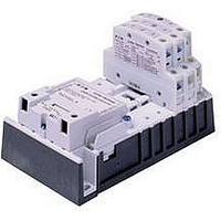
Lighting Contactor
Manufacturer
EATON CUTLER HAMMER
Datasheet
1.A202K2CXM.pdf
(40 pages)
Specifications of C30CNE20A0
No. Of Poles
2
Contact Configuration
DPST-NC
Relay Mounting
DIN Rail
Coil Voltage Vac Nom
120V
Contact Current Max
30A
Mounting Type
DIN Rail
External Height
187.6mm
Continuous Load Current
30A
Operating Voltage
600VAC
Switching Current Ac1
30A
Switching Current Ac3
30A
Load Current Inductive
30A
Contactor Direction
Reversing
Rohs Compliant
No
Lead Free Status / RoHS Status
Contains lead / RoHS non-compliant


June 2008
Product Description
The Cutler-Hammer
Contactor from Eaton’s electrical busi-
ness provides a safe and convenient
means for local or remote switching of
relatively large tungsten, fluorescent
or mercury arc lamp loads.
Application Description
■
■
Wiring Diagrams
Figure 37-8. Standard Wiring
Figure 37-9. Two-Wire Control
CA08102001E
The standard wiring of an A202 con-
tactor can be controlled by a separate
customer supplied single-pole double-
throw controlling station.
Two-wire control can be accom-
plished with a customer supplied
relay with 1NO/1NC auxiliary
contacts, wire as shown.
The Magnetically Latched Lighting
Contactors are designed to withstand
the large initial inrush currents of
tungsten lamp loads without contact
welding.
The A202 Contactors are fully rated
devices that do not require de-rating
similar to standard motor control
contactors.
60A Size
®
A202 Lighting
Control
Switch
■
Features
■
■
■
Operation
A permanent magnet is built into the
contactor structure that will maintain
the contactor in its energized state
indefinitely without using control
power. When energized, a DC current is
applied to the latch coil, producing a
magnetic field that reinforces the polar-
ity of the permanent magnet, pulling in
the contactor. The coil clearing interlock
disconnects the current to the coil. In
order to drop out the contactor, it is
necessary to apply a field through the
STOP coil in the reverse direction to the
permanent magnet. This momentarily
cancels the magnetic attraction and the
contactor drops out.
CM
For more information visit: www.eaton.com
The Magnetically Latched Lighting
Contactor provides effective control
in applications such as office build-
ings, industrial plants, hospitals,
stadiums, airports, etc.
Designed and tested specifically for
lighting and resistive loads
Easy to install and maintain
No control power necessary to
maintain contact closure
Typical
Control
Station
Lighting Contactors
Open Control
A202 Magnetically Latched
Open
CM
Control Line
Line
Close
Neutral
Line
or
CM
CM
Close
Open
3
2
L2
L2
3
2
(+)
(+)
Two-Wire Control
Standard Wiring
Black
Black
ON
ON
White
White
Red
Red
AC
AC
OFF
OFF
Instructional Leaflets
IL16965 30A (2, 3, 4, 5 Poles)
IL16966 60 – 200A (2, 3, 4, 5 Poles)
Standards and Certifications
■
■
Technical Data and
Specifications
■
■
■
Accessories
See A200 NEMA Contactor Accessories,
Page 33-166 – 33-168.
(+)
(+)
(–)
(+)
(+)
(–)
UL Listed File # E44424, Guide NRNT
CSA Certified File # LR39402,
Class 3231-01
Terminals
❑
❑
Ballast load: 600 AC, breaking all
lines
Tungsten lamp loads, maximum
volts
❑
❑
AC
AC
All except 30A devices: Cu/Al
30A devices: Cu only
Line-to-line: 480V AC
Line-to-neutral: 277V AC
Red
Red
Red
Red
Load
Load
Line
Line
Auxiliary
(Option)
Auxiliary
Contact
(Option)
Contact
37-17
37
Related parts for C30CNE20A0
Image
Part Number
Description
Manufacturer
Datasheet
Request
R

Part Number:
Description:
PROGRAMMABLE LOGIC CONTROLLER
Manufacturer:
EATON CUTLER HAMMER
Part Number:
Description:
Pm Power Pro 3000/5000 A-B Accel/On Interface
Manufacturer:
EATON CUTLER HAMMER
Part Number:
Description:
Handle Tie Bar For (2) - 1 Pole Type BR Breakers
Manufacturer:
EATON CUTLER HAMMER
Part Number:
Description:
Type CH Breaker 150A/2 Pole 120/240V 10K
Manufacturer:
EATON CUTLER HAMMER
Part Number:
Description:
Tenant Branch Breaker 125A/3 Pole 120/240V 42K
Manufacturer:
EATON CUTLER HAMMER
Part Number:
Description:
Type CL Breaker 25A/1Pole 120/240V 10K-Classified 1" Ckt Bkr
Manufacturer:
EATON CUTLER HAMMER
Part Number:
Description:
FD BREAKER 1P 80 AMP WITH LOAD ONLY TERMINALS
Manufacturer:
EATON CUTLER HAMMER
Part Number:
Description:
GD 2 POLE BREAKER, 25 AMP, SINGLE PACKED
Manufacturer:
EATON CUTLER HAMMER
Part Number:
Description:
Handle Tie Bar For (2) - 1 Pole Type BR Breakers
Manufacturer:
EATON CUTLER HAMMER
Part Number:
Description:
Type CL Breaker 25A/1Pole 120/240V 10K-Classified 1" Ckt Bkr
Manufacturer:
EATON CUTLER HAMMER