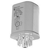
750XBXH-24A Magnecraft / Schneider Electric, 750XBXH-24A Datasheet - Page 3

750XBXH-24A
Manufacturer Part Number
750XBXH-24A
Description
INTERFACE RELAY, DPDT, 24VAC, 72OHM
Manufacturer
Magnecraft / Schneider Electric
Datasheet
1.750XBXH-120A.pdf
(4 pages)
Specifications of 750XBXH-24A
Coil Voltage Vac Nom
24V
Contact Current Max
12A
Contact Voltage Ac Nom
240V
Contact Voltage Dc Max
28V
Coil Resistance
72ohm
Contact Configuration
DPDT
Average Power Consumption
1.2VA
Contact Form
DPDT
Current, Rating
12 A
Dielectric Rating
2500 V (RMS) (Coil to Contact)
Dimensions
2.28 in. (Max.) L x 1.37 in. (Max.) W x 1.39 in. H (Max.)
Function
Power
Material, Contact
Silver Alloy
Mounting Type
PCB
Number Of Pins
8
Relay Type
Electro Mechanical
Resistance, Coil
72 Ohms
Standards
UL, RoHS
Temperature, Operating, Maximum
50 °C
Temperature, Operating, Minimum
-45 °C
Termination
Solder
Voltage, Control
24 VAC
Voltage, Rating
300 VAC
Coil Voltage
24 VAC
Power Consumption
0.9 W
Contact Material
Silver Alloy
Lead Free Status / RoHS Status
Lead free / RoHS Compliant
12
14
11
A1
1
4
2
3
12
14
11
A1
1/46
1
4
3
2
12
14
11
A1
4
3
1
2
14
12
11
A1
3
1
2
4
NEMA
NEMA
General Specifications
NEMA
IEC
22
24
21
UL Listed When Used
6
IEC
5
7
Contact Characteristics
Number and type of Contacts
Contact materials
Thermal (Carrying) Current
Maximum Switching Voltage
Switching Current @ Voltage
Minimum Switching Requirement
Coil Characteristics
Voltage Range
Operating Range
Average consumption
Drop-out voltage threshold
Performance Characteristics
Electrical Life (UL508)
Mechanical Life
NEMA
Operating time (response time)
Dielectric strength
Environment
Product certifications
Ambient air temperature
around the device
Vibration resistance
Shock resistance
Degree of protection
Weight
IEC
24
22
21
With Magnecraft
File No. E209950
6
IEC
5
7
UL Recognized
750H Hermetic Octal Relays, 11-Pin/3PDT, 12 Amp Rating (DC & AC)
C
Sockets.
U L
22
24
31
A2
5
6
8
7
24
31
A2
22
5
6
8
7
11
10
A2
32
34
31
US
8
9
11
10
A2
34
31
32
8
9
A1
14
A1
14
14
3
2
11
14
A1
3
12
2
11
3
Wiring Diagram
A1
4
12
12
3
1
4
Bottom View
2
12
4
1
NEMA
11
2
22
4
5
NEMA
IEC
750XCX
11
22
5
IEC
1
NEMA
21
1
5
21
NEMA
IEC
6
22
5
8
6
IEC
22
8
11
31
24
11
31
24
6
7
31
7
24
6
7
31
A2
7
10
24
A2
10
32
8
% of Nominal
Operations @ Rated Current
Unpowered
Between coil and contact
Between poles
Between contacts
Standard version
Storage
Operation
Operational
9
A2
Class 1, Division 2
certification for
hazardous locations
32
8
9
A2
34
34
(UL 508)
(50.3)
(50.3)
2.1
2.1
(50.3)
(50.3)
2.1
2.1
~
~
~
~
~
~
~
~
~
General Purpose
General Purpose
Pilot Duty
Resistive
grams
Units
Vrms
Vrms
Vrms
mA
VA
g-n
g-n
HP
HP
W
ms
°C
°C
A
V
V
V
Sealed for wash-down
conditions
Gold Flashed Contacts
1.44 MAX
1.44 MAX
(36.6)
(36.6)
12A @ 240V 50/60Hz
12A @ 120V 50/60Hz
1.44 MAX
1.44 MAX
100 @ 5VDC (.5W)
(36.6)
(36.6)
1/2 @ 240 VAC
1/3 @ 120VAC
85% to 110%
80% to 110%
3, 10 - 55 Hz
10,000,000
12A @ 28V
750XCXH
Silver Alloy
-40…+85
-40…+55
100,000
Standard
6….240
6….125
B300
1500
1500
1500
3PDT
IP 67
15%
10%
300
130
1.2
12
20
10
UL
2
1.61 MAX
1.61 MAX
1.61 MAX
1.61 MAX
(40.9)
(40.9)
(40.9)
(40.9)
M agne cr aft S olu tion Guide 1 0 5 A


