C10T13X24D RELECO, C10T13X24D Datasheet - Page 17
C10T13X24D
Manufacturer Part Number
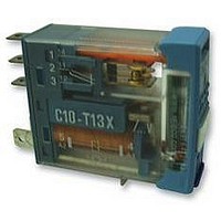
C10T13X24D
Description
RELAY, SPCO, 24VDC
Manufacturer
RELECO
Specifications of C10T13X24D
Coil Voltage Vdc Nom
24V
Contact Current Max
6A
Contact Voltage Ac Nom
250V
Contact Voltage Dc Max
24V
Coil Resistance
742ohm
Relay Mounting
Plug-In
External Width
12.5mm
External Depth
35.4mm
Svhc
No SVHC
Contact Configuration
SPCO
External Height
28.8mm
Rohs Compliant
Yes
Average Power Consumption
1.1VA
Lead Free Status / RoHS Status
Lead free / RoHS Compliant


24-48Vac/dc standard
Electrical and Mechanical Life
100.000 operations at full rated load 20 x 10
mechanical operations measured at 6.000
ops/hour (see table 1).
Temperatures
Operating and storage temperatures are
respectively –20°C...+60°C and –20°C...+100°C.
Coil
The temperature rise in the coil when
permanently energised, at nominal voltage, is
45°C max. at AC and 35°C max. at DC.
All coils are calculated to withstand a permanent
connection at maximum ambient temperature of
60°C and 10% above the nominal voltage.
The coil inrush power of AC coils is approx. 1,3
x nominal power.
Vac/dc Ω ± 10% mA
All values (LED included) measured at U
temperature of 20°C.
* 24Vac and any other coil values, as well as special coils,
are available upon request.
Pull-in voltages
DC and AC/DC relays: 0,75 x U
AC relays: 0,75 x U
Drop-out voltages
DC and AC/DC relays: 0,15 x U
AC relays: 0,35 x U
BX
24
48
Bridge rectifier
A1
A2
Suppressors increase release time approx. 3 times in DC
Lamp circuits
AC 6 … 12
AC 24 … 48
AC 115 … 230
DC 5 … 12
DC 24 … 48
DC 60 … 110
GENERAL INFORMATION
LED & protection circuits available
773
3K5
Voltage
X
31
13
R
Diagrams of additions to the coil
RC protection
A1
A2
115 - 230Vac
A1
A2
Vdc
110
≤ 12V
12
24
5
N
N
(at 50 and 60Hz)
(at 50 and 60Hz)
Ω ± 10%
19K9
X
224
773
45
Polarity protected Free Wheeling Diode
A1
A2
111
A1
A2
BX
+
mA
53
31
≤ 12Vdc
5,5
≥ 24Vdc
N
N
Vac
115
230
N
24
FX
with an ambient
Ω ± 10%
28K3
Use 24Vac/dc*
A2
FX
7K1
A1
A1
A2
+
≥ 24Vac
R
≥ 60Vdc
mA
8,7
4,3
6
IRC SINGLE POLE STANDARD/
LOW SIGNAL LEVEL
• LED Indication as standard (except
• Colour coded lockable test button
• Marking label on relay
• 4.75mm flat blade terminals
• Coil voltage marked on top of relay
• Gold plate option (C10-A18X and
Table 1: C10-A10X Electrical life (ops. x 10
Contacts
Standard material
Optional material
Max. switching current
Peak inrush current (10 ms)
Max. switching voltage, (pollution 3)
Max. switching voltage, (pollution 2)
Max. AC resistive load (table 1)
Max. DC load
Standard types
AC/DC 24, 48
AC
DC
X = LED (standard)
AC/DC rectifier (48V max.) C10-A10B X/ ...V
FWD - polarity protected
RC protection (no LED)
Specifications
Coil power including LED
Operate time + bounce time
Release time + bounce time
Isolation: EN60947 pollution 3, Gr C
Dielectric strength, contact / coil 8 mm / 5 KV
Weight avg.
VA 250
with RC suppression)
C10-T12X)
0,1
10A / 400V AC1
10
C10-A10X...
1
6A / 400V AC15
115, 230
5, 12, 24, 48, 110
Single pole relay, 10A
For lamp, see appropriate diagram
12 14
750
3
11
2
1
(50/60 Hz and DC)
54
code 8 - AgNi + 10µ Au
1250
10 A @ 30V DC1
0,5A @ 110V DC1
A1
A2
5
4
C10-A10 X/ ...V
C10-A10F X/ ...V
C10-A10R / ...V
1,1 VA, 0,65 W
1750
10 + 1 ms
5 + 3 ms
2,5 KVA
(table 2)
21 grs.
250 V
400 V
250 V
2250
AgNi
10 A
30 A
6
)
• BX version — one type fits all!
Contacts
Standard material
Optional material
Switching current
Peak inrush current (5 ms)
Max. switching voltage, (pollution 3)
Max. switching voltage, (pollution 2)
Max. AC resistive load
Max. DC load @ 24 V
Standard types
AC/DC 24, 48
AC
DC
X = LED (standard)
AC/DC rectifier (48V max.) C10-T13B X/ ...V
FWD - polarity protected
RC protection (no LED)
Specifications
Coil power including LED
Operate time + bounce time
Release time + bounce time
Isolation: EN60947 pollution 3, Gr C
Dielectric strength, contact / coil 8 mm / 5 KV
Weight avg.
Table 2: C10-A10X
Volts 25
– 24VDC
– 24VAC
– Not polarity conscious
– Free wheeling diode (VDC)
– RC suppression (VAC)
C10-T13X...
Single pole relay, bifurcated contact
0,1
10
6A / 400V AC1
1
115, 230
5, 12, 24, 48, 110
For lamp, see appropriate diagram
Min. 1mA @ DC 5V
12 14
3
11
2
75
1
(50/60 Hz and DC)
code 2 - AgNi + 10µ Au
code 3 - AgNi + 3µ Au
A1
A2
5
125
4
min. 1 mA; max. 6 A
6A @ 30V DC1
C10-T13 X/ ...V
C10-T13F X/ ...V
C10-T13R / ...V
RELAYS
1,1 VA, 0,65 W
Max. DC load
175
Iow level
10 + 1 ms
5 + 3 ms
1,5 KVA
21 grs.
250 V
400 V
250 V
15 A
225
6 A
Related parts for C10T13X24D
Image
Part Number
Description
Manufacturer
Datasheet
Request
R

Part Number:
Description:
RELAY, SPCO, 24VAC/DC
Manufacturer:
RELECO
Datasheet:
Part Number:
Description:
RELAY, SPCO, 230VAC
Manufacturer:
RELECO
Datasheet:

Part Number:
Description:
RELAY, DPCO, 24VAC/DC
Manufacturer:
RELECO
Datasheet:
Part Number:
Description:
RELAY, DPCO, 12VDC
Manufacturer:
RELECO
Datasheet:
Part Number:
Description:
RELAY, DPCO, 230VAC
Manufacturer:
RELECO
Datasheet:
Part Number:
Description:
RELAY, DPCO, 24VDC
Manufacturer:
RELECO
Datasheet:

Part Number:
Description:
POWER RELAY, SPCO, 24VDC, 10A, PLUG IN
Manufacturer:
RELECO
Datasheet:

Part Number:
Description:
POWER RELAY, DPCO, 115VAC, 10A, PLUG IN
Manufacturer:
RELECO
Datasheet:
Part Number:
Description:
POWER RELAY, DPCO, 24VDC, 10A, PLUG IN
Manufacturer:
RELECO
Datasheet:

Part Number:
Description:
POWER RELAY, 3PCO, 115VAC, 10A, PLUG IN
Manufacturer:
RELECO
Datasheet:

Part Number:
Description:
Power Inductors
Manufacturer:
Mitsumi Electronics
Datasheet:
Part Number:
Description:
Power Inductors
Manufacturer:
Mitsumi Electronics
Datasheet:
Part Number:
Description:
Power Inductors
Manufacturer:
Mitsumi Electronics
Datasheet:

Part Number:
Description:
Power Inductors
Manufacturer:
Mitsumi Electronics, Corp.
Datasheet: