C10T13X24D RELECO, C10T13X24D Datasheet - Page 4
C10T13X24D
Manufacturer Part Number
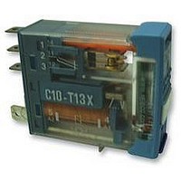
C10T13X24D
Description
RELAY, SPCO, 24VDC
Manufacturer
RELECO
Specifications of C10T13X24D
Coil Voltage Vdc Nom
24V
Contact Current Max
6A
Contact Voltage Ac Nom
250V
Contact Voltage Dc Max
24V
Coil Resistance
742ohm
Relay Mounting
Plug-In
External Width
12.5mm
External Depth
35.4mm
Svhc
No SVHC
Contact Configuration
SPCO
External Height
28.8mm
Rohs Compliant
Yes
Average Power Consumption
1.1VA
Lead Free Status / RoHS Status
Lead free / RoHS Compliant


Contact materials
Silver-nickel (AgNi) and silver-tin oxide
(AgSnO
materials for all models. Other contact
materials are available on request.
Gold Flash
For relays that are intended to be stored or
remain unoperated for any length of time, a
0,2µ layer of gold protects the contacts
from oxidisation.
Gold Plating
A 10µ plate of gold increases the operat-
ional reliability. They should be used for
switching low level currents.
Contact Resistance
Contact resistance is dependent on
contact material, contact pressure and
contact contamination.
High contact resistance raises the temp-
erature of the contacts, therefore reduc-
ing their working life.
Typical contact resistance of the MR-C and
QR-C relays is 50 m .
Contacts gap
Contact gap and opening speed of the
contacts have an influence on the length
and the duration of the arc.
In the case of AC, a gap of 0,5 mm is
sufficient to quench the arc which occurs
automatically at the “zero point” of the
cycle.
In the case of DC, the arc only quenches
when the contact gap is sufficient for the
voltage and current applied.
Please see tables of “Max. DC current”.
Coil Materials
Coils bobbins are moulded in poly-
butylene with fibreglass (130° C).
Enamelled wires of Class F specification
are used (155° C).
They are wound on automatic precision
winding machines, with the number of
turns and wire tension accurately regulated
and monitored.
Tolerances
Coil resistance is measured at 20° C and is
regulated within ± 10% of specified value.
Standard Windings
The coil voltages indicated in the catal-
ogue refer to standard windings.
Other coil voltages are available, includ-
ing products for series connection and
amperometric applications.
Please consult your distributor for details.
2
) are
used as standard contact
Maximum Intensity
The “Max. switching current” indicated in
every model, refers to the maximum stable
current which should be possible in
permanent conduction (I
In
switchingcurrent”
support is the same for all the values of
voltages
specified in every model.
The product of the intensity and the volt-
age applied should not be higher than the
values specified as “Max. AC load”.
In the case of DC, the “Max. switching
current” must be less than the current that
causes the continuous arcing.
The tables of “Max. DC current” show the
possible values of intensity in relation to
the applied voltage.
Maximum Voltage
The maximum voltage on the contacts
depends on the insulation between each
contact (pole to pole) and between all
contacts and the coil.
The EN60947 and VDE 0110 standards set
out the maximum voltage values, taking
into consideration the quality of the
insulation materials, pollution degree as
well as the shape and dimensions of the
contact barriers (creepage distance).
Contacts in series
The connection of two or more contacts in
series is equivalent to multiplying the
contact gap by that amount. By using this
method, a greater break capacity is
achieved for DC switching.
Minimum working voltage (pull in)
This is the minimum voltage that must be
supplied to the coil to ensure that the relay
energises, the contacts change over and are
positively held in place without any vibration.
The values of voltage specified are those at
or above which the relay must pull in.
Maximum release voltage (drop out)
This is the voltage at which the relay de-
energises, the contacts change over and are
positively held in place without any
vibration.
The values of voltage specified are those at
or below which the relay must drop out.
GENERAL INFORMATION
the
DC relays
AC relays
DC relays
AC relays
case
of the “Max. switching voltage”
80% Un
15% Un
80% Un
10% Un
of
41
that the relay can
AC,
TH
).
the
“Max.
Contacts in parallel
The connection of two or more contacts in
parallel does not mean that it is poss-ible
to switch a greater load. However,
the stable current and the operational
reliability of the relay is increased.
Double break contacts
The double break contact arrangement is
equivalent to two contacts connected in
series.
The
corresponds to only one contact. This
system allows for higher DC operating
voltages.
Bifurcated (twin) contacts
The contact blade is divided into two parts,
each with its own contact.
Both contacts press down each on their
own independent fixed contacts.
This system is particularly good for reliably
switching at very low levels.
Contact protection
The electrical life of contacts can be
prolonged by components which eliminate
or reduce the back EMF transients.
These voltages are generated by the
reactive component of the load on
disconnection,
duration and the temperature of the arc.
For AC, RC suppressors or varistors can
be connected in parallel with the load or
the contacts.
For DC with an inductive load, the best
method is to connect a diode in parallel
with the load.
Ambient temperature
The ambient temperature has an influence
on the coil resistence and on its thermal
dissipation capacity.
Curve 1 represents the variations of the pull
in voltage (% U
ambient temperature (T).
Curve 2 indicates the maximum values of
the voltage applied (U
ation with the nominal voltage (U
ambient temperature (T).
Ub/Un
1,7
1,5
1,3
1,1
0,9
0,7
0,5
-20
maximum
-5
10
1
which
n
25
) in relation with the
intensity
2
b
) to the coil in rel-
40
increases
RELAYS
55
supported
70 TºC
n
) at the
the
Related parts for C10T13X24D
Image
Part Number
Description
Manufacturer
Datasheet
Request
R

Part Number:
Description:
RELAY, SPCO, 24VAC/DC
Manufacturer:
RELECO
Datasheet:
Part Number:
Description:
RELAY, SPCO, 230VAC
Manufacturer:
RELECO
Datasheet:

Part Number:
Description:
RELAY, DPCO, 24VAC/DC
Manufacturer:
RELECO
Datasheet:
Part Number:
Description:
RELAY, DPCO, 12VDC
Manufacturer:
RELECO
Datasheet:
Part Number:
Description:
RELAY, DPCO, 230VAC
Manufacturer:
RELECO
Datasheet:
Part Number:
Description:
RELAY, DPCO, 24VDC
Manufacturer:
RELECO
Datasheet:

Part Number:
Description:
POWER RELAY, SPCO, 24VDC, 10A, PLUG IN
Manufacturer:
RELECO
Datasheet:

Part Number:
Description:
POWER RELAY, DPCO, 115VAC, 10A, PLUG IN
Manufacturer:
RELECO
Datasheet:
Part Number:
Description:
POWER RELAY, DPCO, 24VDC, 10A, PLUG IN
Manufacturer:
RELECO
Datasheet:

Part Number:
Description:
POWER RELAY, 3PCO, 115VAC, 10A, PLUG IN
Manufacturer:
RELECO
Datasheet:

Part Number:
Description:
Power Inductors
Manufacturer:
Mitsumi Electronics
Datasheet:
Part Number:
Description:
Power Inductors
Manufacturer:
Mitsumi Electronics
Datasheet:
Part Number:
Description:
Power Inductors
Manufacturer:
Mitsumi Electronics
Datasheet:

Part Number:
Description:
Power Inductors
Manufacturer:
Mitsumi Electronics, Corp.
Datasheet: