45.085 400VAC BROYCE CONTROL, 45.085 400VAC Datasheet
45.085 400VAC
Manufacturer Part Number
45.085 400VAC
Description
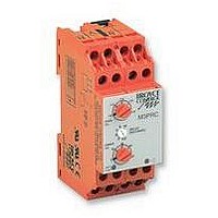
RELAY, LOSS/UNDER/OVER VOLT, 3PHASE
Manufacturer
BROYCE CONTROL
Datasheet
1.45.085_400VAC.pdf
(1 pages)
Specifications of 45.085 400VAC
Contact Configuration
2PCO
Power Consumption
3.9VA
Supply Voltage Max
400VAC
Relay Mounting
DIN Rail
Control Voltage Type
AC
Contact Current Ac Max
8A
Contact Current Dc Max
8A
Adjustment Type
Knob
45085
q
q
q
q
q
q
Troubleshooting
i
operates immediately the supply is applied. The delay
prevents either relay from energising if the measured
voltage is above or below the set level.
Supply/monitoring
(phase to phase)
Supply variation:
Isolation:
Rated impulse withstand
Power consumption:
(max.)
*Voltage setting:
Upper trip level:
Lower trip level:
Accuracy:
Hysteresis:
Reaction time:
Time delay (t):
On delay (Td):
Ambient temperature:
Relative humidity:
Output:
Output rating:
Electrical life:
Housing:
Weight:
Mounting option:
Terminal conductor
Approvals:
voltage Un*:
voltage:
size:
BEFORE INSTALLATION, ISOLATE THE SUPPLY
Connect the unit as shown in the diagram above.
Set 'over trip level' and 'under trip level'.
Set 'nominal voltage' switch as required.
Apply power (green LED on, red LED on, contacts 15 /
18 and 25 / 28 closed).
Check wiring and voltage present.
use of such information shall be entirely at the user's own risk
The unit incorporates a "power on delay (Td)" which
accurate (subject to change without prior notice); however,
The information provided in this literature is believed to be
I
TECHNICAL SPECIFICATION
H+44 (0) 1902 773746 G+44 (0) 1902 420639 Email: sales@broycecontrol.com Web: http://www.broycecontrol.com
NSTALLATION AND SETTING
DETECTS UNDER OR OVER VOLTAGE
CONDITION
SEPARATE ADJUSTMENT FOR UPPER LEVEL
AND LOWER LEVEL
SELECTABLE NOMINAL VOLTAGE*
ADJUSTABLE DELAY FOR EACH LEVEL
OUTPUT RELAY 8A (x2)
SUPPLY / RELAY INDICATION
Installation work must be carried
out by qualified personnel.
FUNCTION DIAGRAM
DIAGRAMMEDE FONCTION
FUNKTIONSDIAGRAM
220, 400*, 480, 600V AC
45 - 65Hz
Galvanic isolation (Integral transformer)
0.85 - 1.15 x Un
Overvoltage category III
4kV (1.2/50 S) < 480V
6kV (1.2/50 S) < 600V
380, 400 or 415V selectable by rotary
switch (only available on 400V unit)
1.02 -1.10 x Un
0.90 - 0.98 x Un
< 2%
0.1 - 10S (-10/+30% @ max.)
(N.B. t = set delay + reaction time)
-20 to +60 C
+95%
2 x C.O.
AC1 250V AC 8A (2000VA)
AC15 250V AC 6A
DC1 25V DC 8A (200W)
to UL94 VO
to BS5584:1978
(EN50 002, DIN 46277-3)
Conforms to UL, CUL, CSA & IEC.
CE and
< 200mS (worst case = 5 x )
3.9VA (red / blue phases)
0.2VA (yellow phase)
2%
5S (worst case = Td/2)
150,000 (AC1)
320g (< 480V),
2 x 1.5mm
2 x 2.5mm
25, 26, 28
15, 16, 18
Broyce Control Ltd., Pool Street, Wolverhampton, West Midlands WV2 4HN. England
3 Phase Under / Over Voltage Relay plus Time Delay
Relais 3 phases sous / sur voltage plus délai de temps
3 Phasen Relais Unter / Über Spannung plus Zeitverzögerung
Compliant
2
2
R
Y
B
stranded wire
solid wire
Td
340g (600V)
t
t
q
q
q
q
q
q
Intervention (pour régler un problème)
i
immédiatement l'alimentation demandée. Le délai
empêche chaque relais de s'activer si le voltage mesuré est
au dessus ou au dessous des délais fixés.
Voltage d ' alimentation
Variation d ' alimentation:
Isolement:
Impulsion nominale
Puissance consommée:
(max.)
*Réglage du voltage:
Niveau déclancheur
Précision:
Hystérèse:
Temps de réaction ():
Délai de temps (t):
Activation du délai (Td):
Température ambiante:
Humidité relative:
Sortie:
Mesure de sortie:
Durée de vie électrique:
Boitier:
Poids:
Option de montage:
Taille du conducteur
Homologations:
contrôlée Un* (mise en phase):
résistant à la tension:
supérieur:
inférieur:
terminal:
réserve de changement sans avis préalable) toutefois aux risques et
AVANT MONTAGE, ISOLER L ' ALIMENTATION
Branchement comme indiqué dans le diagramme ci-
dessus.
Régler les 'niveaux de déplacement au-dessus et au-
dessous'.
Fixer le voltage nominal comme exigé.
Appliquer la puissance (LED verte allumée, LED rouge
allumée, contacts 15 / 18 et 25 / 28 fermés).
Vérifier les fils et le voltage présent.
Les indications contenues dans ce document sont exactes (sous
L'unité incorpore un "délai d'allumage (Td)" qui opère
MONTAGE ET MISE AU POINT
FICHES TECHNIQUES
DÉTECTE LES CONDITIONS DE SOUS-VOLTAGE
OU DE SUR-VOLTAGE
AJUSTEMENT SÉPARÉ POUR LE NIVEAU HAUT
ET LE NIVEAU BAS
VOLTAGE NOMINAL SÉLECTIONNABLE*
DÉLAI AJUSTABLE POUR CHAQUE NIVEAU
RELAIS DE SORTIE 8A (x2)
D ' ALIMENTATION / RELAIS INDICATION
menés à bien par le personnel qualifié.
Des travaux d'installation doivent être
HYST
UNDER
OVER
HYST
périls de l ' utilisateur
220, 400*, 480, 600V AC 45 - 65Hz
Isolation galvanique (Transformateur intégral)
0.85 - 1.15 x Un
Survoltage catégorie III
4kV (1.2/50 S) < 480V
6kV (1.2/50 S) < 600V
380, 400, ou 415V
interrupteur rotatif (Seulement disponible sur
unité de 400V)
1.02 - 1.10 x Un
0.90 - 0.98 x Un
0.1 - 10S (-10/+30% @ max.)
(N.B. t = fixer délai + temps de réaction)
-20 à +60 C
+95%
2 x Inverseur
AC1 250V AC 8A (2000VA)
AC15 250V AC 6A
DC1 25V DC 8A (200W)
à UL94 VO
à BS5584:1978
(EN50 002, DIN 46277-3)
Se conformer à UL, CUL, CSA & IEC.
CE et
< 200mS (le plus mauvais cas = 5 x )
3.9VA (rouge / bleu phases)
0.2VA (jaune phase)
2%
5S (le plus mauvais cas = Td/2)
320g (< 480V),
2%
150,000 (AC1)
2 x 1.5mm
2 x 2.5mm
CONNECTION DIAGRAM
DIAGRAMME DE CONNECTION
SCHALTBILDANSCHLUSS
Both relays are
shown in the
de-energised
condition
Déférence
2
2
multi-filaire
toron
sélectionnable par
16 18 25
340g (600V)
15 25
R
28
45085
Y
B
LOAD
q
q
q
q
q
q
Störungsbehebung
i
(Td)" welche sich sofort nach der Stromversorgung
einschaltet. Die Zeitverzögerung verhindert dass sich
irgendein Relais bei Über - oder Unterspannung des
festgelegten Stands einschaltet.
Stromversorgung /
Spannungskontrolle Un*:
(phase zu phase)
Wechselversorgung:
Isolation:
Nenn-Impulse
Energieverbrauch:
(max.)
*Spannungseinstellung:
Standauslösser
Genauigkeit:
Hysterese:
Reaktionzeit:
Zeitsteuerung (t):
An - Verzögerung (Td):
Umgebungstemperatur:
Allgemeiner
Ausgang:
Ausgangsleistung:
Elektrische Lebensdauer:
Gehäuse:
Gewicht:
Befestigungswahl:
Anschlussklemme
Genehmigungen:
Spannungswiderstand:
oberer:
unterer:
Feuchtigkeitsgehalt:
/ Kabelgrösse:
VOR EINBAU DIE STROMVERSORGUNG
ISOLIEREN
Stromversorgung anschliessen wie im Schaltbild unten
angezeigt.
Einstellung der 'unter - und über Standverschiebung'.
Nennspannung wie Schalter einstellen
Energie anbringen (LED grün an, LED rot an, Kontakte
15 / 18 und 25 / 28 geschlossen).
Überprüfung von Leitungen und gegenwärtiger
Spannung.
Angaben, (Änderungen vorbehalten) jedoch diese Änderungen
3 Phase Supply
Es handelt sich in diesen Unterlagen um uns genau bekannte
In der Einheit einbegriffen, ist eine "Zeitverzögerung
EINBAU UND EINSTELLUNG
TECHNISCHE DATEN
R (L1)
B (L3)
Monitored
Y (L2)
ERKENNT DEN UNTER - ODER
ÜBERSPANNUNGSSTAND
GETRENNTE EINSTELLUNG FÜR OBEREN UND
UNTEREN STAND
NENNSPANNUNG ANSTEUERBAR*
EINSTELLBARES VERZÖGERUNG FÜR JEDEN STAND
AUSGANGSRELAIS 8A (x2)
VERSORGUNGS / RELAIS INDIKATION
Installation Arbeit muß von qualifiziertem
laufen auf eigene Gefahr des Benutzers.
Personal durchgeführt werden.
MOUNTING DETAILS
INSTRUCTIONS DE MONTAGE
MONTAGEAUFÜHRUNGEN
Width / largeur / Breite. 45 mm
Insert screwdriver
to release clip
220, 400*, 480, 600V AC 45 - 65Hz
Galvanische Isolierung (Integraltransformator)
0.85 - 1.15 x Un
Überspannung Kategorie III
4kV (1.2/50 S) < 480V
6kV (1.2/50 S) < 600V
380, 400 oder 415V Ansteuerbar durch
Drehschalter (Nur verfügbar bei 400V
Einheit)
1.02 - 1.10 x Un
0.90 - 0.98 x Un
0.1 - 10S (-10/+30% @ max.)
(N.B. t = Verzögerung festlegen +
Reaktionzeit)
-20 bis +60 C
+95%
2 x Wechsler
AC1 250V AC 8A (2000VA)
AC15 250V AC 6A
DC1 25V DC 8A (200W)
bis UL94 VO
bis BS5584:1978
(EN50 002, DIN 46277-3)
Anmerkung UL, CUL, CSA & IEC.
CE und
< 200mS (schlimmster Fall = 5 x )
3.9VA (rot / blau phase)
0.2VA (gerb phase)
2%
2%
5S (schlimmster Fall = Td/2)
150,000 (AC1)
320g (<480V), 340g (600V)
2 x 1.5mm
2 x 2.5mm
2
2
Übereinstimmung
Litze
Festdraht
78
74
45085-1-B
99
Related parts for 45.085 400VAC
Image
Part Number
Description
Manufacturer
Datasheet
Request
R

Part Number:
Description:
RELAY, CONDUCTIVE LEVEL CONTROL
Manufacturer:
BROYCE CONTROL
Datasheet:
Part Number:
Description:
RELAY, CONDUCTIVE LEVEL CONTROL, 230VAC
Manufacturer:
BROYCE CONTROL
Datasheet:

Part Number:
Description:
RELAY, THERMISTOR
Manufacturer:
BROYCE CONTROL
Datasheet:

Part Number:
Description:
TEMPERATURE CONTROLLER, PT100
Manufacturer:
BROYCE CONTROL
Datasheet:

Part Number:
Description:
RELAY, UNDER/OVER CURRENT
Manufacturer:
BROYCE CONTROL
Datasheet:

Part Number:
Description:
RELAY, MULTIFUNCTION, CURRENT
Manufacturer:
BROYCE CONTROL
Datasheet:
Part Number:
Description:
RELAY, 3PHASE ASYMMETRY, 400VAC
Manufacturer:
BROYCE CONTROL
Datasheet:
Part Number:
Description:
RELAY,EARTH LEAKAGE VARIABLE
Manufacturer:
BROYCE CONTROL
Datasheet:
Part Number:
Description:
RELAY,EARTH LEAKAGE VARIABLE PANEL
Manufacturer:
BROYCE CONTROL
Datasheet:

Part Number:
Description:
RELAY, SEQUENCE/LOSS
Manufacturer:
BROYCE CONTROL
Datasheet:

Part Number:
Description:
RELAY, PHASE SEQUENCE FAILURE
Manufacturer:
BROYCE CONTROL
Datasheet:
Part Number:
Description:
RELAY,SEQUENCE/LOSS, 3PHASE
Manufacturer:
BROYCE CONTROL
Datasheet:

Part Number:
Description:
INDICATOR, 3 PHASE
Manufacturer:
BROYCE CONTROL
Datasheet:

Part Number:
Description:
RELAY, SEQUENCE/LOSS, 3PHASE
Manufacturer:
BROYCE CONTROL
Datasheet:

Part Number:
Description:
RELAY, SEQUENCE/LOSS, 3PHASE
Manufacturer:
BROYCE CONTROL
Datasheet: