G4A-1A-E DC12 Omron, G4A-1A-E DC12 Datasheet
G4A-1A-E DC12
Specifications of G4A-1A-E DC12


Related parts for G4A-1A-E DC12


G4A-1A-E DC12 Summary of contents
Page 1
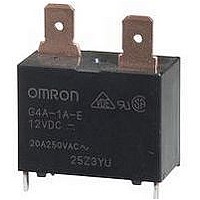
... Standard model available with flux protection construction. • RoHS Compliant Ordering Information Classification #250 tab terminals/PCB coil terminals PCB terminals/PCB coil terminals Note: When ordering, add the rated coil voltage to the model number. Example: G4A-1A-E DC12 Rated coil voltage Model Number Legend G4A - DC 1 ...
Page 2
... Mechanical: Motor load: Inverter load: Operating: −20°C to 60°C (with no icing) Ambient temperature Ambient humidity Operating 85% Weight Approx Note: The data shown above are initial values. G4A 222 Power PCB Relay 12 VDC 75 mA 160 Ω 0.8 H 1.1 H Switching frequency ON:1.5 s OFF:1 ...
Page 3
... Mounting Holes (Bottom View) +0.1 Four, 1.8 dia. 0 Terminal Arrangement /Internal Connections (Top View) (Bottom View) Tab Terminal PCB Terminal Mounting Holes (Bottom View) +0.1 Four, 1.8 dia. 0 Terminal Arrangement /Internal Connections (Bottom View) G4A 223 Power PCB Relay ...
Page 4
... Do not apply excessive force on the terminals when mounting or dismounting the relay. The following positive-lock connectors made by AMP are recommended. Type #250 terminals (width: 6.35 mm) Note: The numbers shown in parentheses are for air-feeding. G4A 224 Power PCB Relay Receptacle terminals AMP 170333-1 (170327-1) ...
Page 5
... Amendment: These Terms constitute the entire agreement between Buyer and Seller relating to the Products, and no provision may be changed or waived unless in writing signed by the parties. 5. Severability: If any provision hereof is rendered ineffective or invalid, such provision shall not invalidate any other provision. Power PCB Relay G4A ...
Page 6
... E. Commerce Drive, Suite B Schaumburg, IL 60173 847-882-2288 06/09 Cat. No. X301-E-1 G4A Power PCB Relay 2. Programmable Products. Seller shall not be responsible for the user's pro- gramming of a programmable product, or any consequence thereof. 3. Performance Data. Performance data given in this publication is provided as a guide for the user in determining suitability and does not constitute a war- ranty ...