MY2N 220/240ACS Omron, MY2N 220/240ACS Datasheet
MY2N 220/240ACS
Specifications of MY2N 220/240ACS


Related parts for MY2N 220/240ACS


MY2N 220/240ACS Summary of contents
Page 1
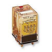
... General-purpose Relay An Improved Miniature Power Relay with Many Models for Sequence Control and Power Applications A wide range of relay variations including ones with operation indicators, high-capacity capability, built-in diodes, etc. Arc barrier standard on 3- and 4-pole relays. Withstand voltage: 2,000 VAC. Ordering Information ...
Page 2
... Add “-G” to the model number if mounting studs are required (e.g., MY4-G). 4. The standard contacts for MY2Z-series Relays and for the MY4Z are gold-plated. **5. Models denoted by “–––” will be manufactured upon request. Ask your OMRON representative. 6. The following variations are also available. ...
Page 3
... H 86. PCB terminals Clip Socket Clip PY08(QN) PYC-P PY11(QN) PY14(QN) PY08(QN) PYC-1 PY08(QN) PYC-P2 PY11(QN) PY14(QN) PY08(QN) PYC-1 PY11(QN) PY14(QN) Must Max. Power release voltage consum. consum. (A (Approx rated voltage 30% 110% 1 min. (60 Hz) (60 Hz) 0 1.1 VA (60 Hz) (60 Hz) 10% ...
Page 4
... The must operate and must release voltages for High-sensitivity Relays was measured at the rated power supply voltage coil resistance and impedance are provided as reference values (at 60 Hz). 5. Power consumption drop was measured for the above data. When driving transistors, check leakage current and connect a bleeder resistor if required. ...
Page 5
... MY Life Expectancy Characteristics Relays Normal, High-humidity, With test button (except relays with operation indicator), With CR High-capacity With operation indicator or built-in diode With bifurcated contacts High-sensitivity Note: See following tables for real load life expectancies. Life Expectancies Under Real Loads MY2 Rated voltage ...
Page 6
... MY Approved by Standards Some MY Relays are available in models meeting various safety standards. When ordering, you must specify the desired standards. Refer to Ordering Information for specific models. Note that the rat- ing recognized by the various standards sometimes vary from the ratings of the individual relays. ...
Page 7
MY MY4, MY4Z AC resistive load DC resis- tive load DC resis- tive load L Switching voltage (V) Life Expectancy MY1, MY2, MY3 (Resistive Loads) 5,000 110 VAC resistive load 1,000 500 24 VDC resistive load 100 ...
Page 8
MY MY4Z (Resistive Loads) 5,000 1,000 220 VAC resis- 500 tive load 24 VDC resistive load 100 Switching current (A) MY2-Y (Resistive Loads) 5,000 110 VAC resistive load 1,000 500 24 VDC resistive load 100 Switching current (A) 8 MY4Z ...
Page 9
... MY Dimensions Note: All units are in millimeters unless otherwise indicated. Relays with Solder Terminals MY1 35.5 max. MY2, MY2-TU, MY2N, MY2N-D2 0.5 36 max. Terminal arrangement/internal connections 2.6 Five, 1.2 dia. x 2.2 elliptic holes 0.5 28 max. 6.3 21.5 6.4 max. Standard 2.6 Eight, 1.2 dia. x 2.2 ellipse holes ...
Page 10
... Note type is equipped with a coil disconnection self– diagnostic function not reverse the polarity of DC relays. MY4N-D2 Note: The MYC3 High–sensitivity Relay incorporates a semi–conductor. A surge–absorb element should be attached the relay is used with a load that can generate noise surge current cannot be avoided in the circuit ...
Page 11
... The above dimensions are for -G type relays (with mounting studs). 3. Test button I4: AC with red push button DC with blue push button Note: The terminal arrangement and internal connections of the above relays are as same as these of MY 2.6 Fourteen, 1.2 dia. x 2.2 ellipse holes. 0.5 28 max ...
Page 12
... Relays with PCB Terminals MY -02 MY4-02 (4PDT) 0.5 36 max. Note: 1. The figures in the parentheses are for MY4-02. 2. The above dimensions also apply to the SPDT, DPDT, and 3PDT relays. 4. The internal connections of the above relays are as same as these of MY relays (N)- max. 6.3 21.5 max ...
Page 13
... MY4F 2 0.5 36 max . Note: 1. The above dimensions also apply to the SPDT, DPDT, and 3PDT relays. 2. The internal connections of the above relays are as same as these of MY relays. Mounting Height with Socket DIN rail/surface–mounting socket MY 70 (87) PYF A(-E) Note: 1. The PTF-A can be rail–mounted or screw-mounted. ...
Page 14
... Hold-down Clips Hold-down clips are used to hold relays to sockets and prevent them from coming loose due to vibration or shock. Connection to socket PYC-A1 PYC-P PY14-3 (for 4PDT) with operation check terminal Three, 1.2 dia holes Two dia. holes Short-circuit lead wire ...
Page 15
... Connections Do not reverse polarity when connecting DC-operated relays with built-in diodes or indicators or high-sensitivity DC-operated relays. Mounting Whenever possible, mount relays so that it is not subject to vibration or shock in the same direction as that of contact movement. The test button should be be pointed upwards when mounting (refer to the right figure) ...
Page 16
... ALL DIMENSIONS SHOWN ARE IN MILLIMETERS. To convert millimeters into inches, multiply by 0.03937. To convert grams into ounces, multiply by 0.03527. Cat. No. J01-E1-11 In the interest of product improvement, specifications are subject to change without notice. OMRON Corporation Relay Division 28th Fl., Crystal Tower Bldg. 1-2-27, Shiromi, Chuo-ku, Osaka 540 Japan ...