G2R-1-T 12VDC Omron, G2R-1-T 12VDC Datasheet
G2R-1-T 12VDC
Specifications of G2R-1-T 12VDC


Related parts for G2R-1-T 12VDC


G2R-1-T 12VDC Summary of contents
Page 1
... PCB Relay The Redesigned G2R Power Relay Flux protection, pre-tinned terminals now standard. High-sensitivity (360 mW) and high-capacity (16 A) types available. Double-winding latching type also available. Plug-in and quick-connect terminals available. Models meeting SEV and SEMKO, or VDE standards available. Ordering Information Classification ...
Page 2
... G2R Note: 1. When ordering, add the rated coil voltage to the model number. Example: G2R-1A 12 VDC Rated coil voltage 2. OMRON has also prepared the above relays with AgSnIn contacts, which are more tolerant of large inrush currents and physical movement compared with relays with standard contacts. When ordering, add “-ASI” to the model number. ...
Page 3
... Bifurcated 3: Bifurcated crossbar Accessories (Order Separately) Connecting Sockets Number of poles Applicable relay model 1 pole G2R-1-S(N)(D)(ND) G2R-13-S (G2R-1A3-S) 2 poles G2R-2-S(N)(D)(ND) Note: See “ Dimensions ” for details on socket size. Mounting Track Applicable socket Track connecting socket Mounting track End plate ...
Page 4
... Set coil: Approx. 850 mW; Reset coil: Approx. 600 mW G2R 48 VDC 100 VDC 11.5 mA 5.3 mA 4,170 18,860 13.86 67.2 27.71 93.2 48 VDC 7.5 mA 6,400 31.20 62 ...
Page 5
... A at 250 1 250 VDC VAC; VAC VDC 2 VDC 4 A 380 VAC, 125 VDC 4 A 1,500 VA, 1,000 VA, 375 VA, 120 W 120 VDC G2R High-capacity 1 pole Resistive load Inductive load (cos = 1) (cos = 0. 250 VAC; 250 VAC VDC VDC 16 A 380 VAC, 125 VDC 16 A ...
Page 6
... DC coil: 20,000,000 operations min. (at 18,000 operations/hr) 100,000 operations min. (at 1,800 operations/hr under rated load) – (with no icing) 35% to 85% G2R Inductive load (cos = 0.4; L ms) 1 250 VAC VDC 375 VA pole 2 when no energized (approx. 10G) ...
Page 7
... SPST-NO G2R-1A4 G2R-1A-H G2R-1A-S G2R-1A-T G2R-1-E SPDT G2R-1A-E SPST-NO G2R-2 DPDT G2R-24 G2R-2-H G2R-2-S G2R-2A DPST-NO G2R-2A4 G2R-2A-H G2R-2A-S G2R-1A-ASI SPST-NO 1 pole 50 m max. 1,800 operations/hr (under rated load) 5,000 VAC, 50/60 Hz for 1 min between coil and contacts*; 3,000 VAC, 50/60 Hz for 1 min between ...
Page 8
... G2R-1-H G2R-1-S G2R-1-T G2R-1A SPST-NO G2R-1A4 G2R-1A-H G2R-1A-S G2R-1A-T G2R-1-E SPDT G2R-1A-E SPST-NO G2R-2 DPDT G2R-24 G2R-2-H G2R-2-S G2R-2A DPST-NO G2R-2A4 G2R-2A-H G2R-2A-S G2R-1A-ASI SPST-NO SEV Contact form 1 poles 3 to 110 VDC 2 poles 3 to 240 VAC SEMKO Contact form 1 poles 3 to 110 VDC 2 poles TÜ ...
Page 9
... G2R Engineering Data Max. Switching Capacity Flux Protection/Plug-in Relays G2R-1, G2R-1A, G2R-1-S, G2R-1-T, G2R-1A-T AC inductive load AC (cos = 0.4) resistive load DC resistive load DC inductive load (L ms) Switching voltage (V) G2R-1-H, G2R-1A-H, G2R-2 G2R-2A, G2R-2-S AC inductive load AC (cos = 0.4) resistive load DC resistive load DC inductive load ...
Page 10
... G2R-14, G2R-1A4 AC inductive load AC (cos = 0.4) resistive load DC inductive load (L ms) DC resistive load Switching voltage (V) Life Expectancy Flux Protection/Plug-in Relays G2R-1, G2R-1A, G2R-1-S, G2R-1-T, G2R-1A-T 5,000 250-VAC/30-VDC 1,000 resistive load 250-VAC inductive load 500 (cos = 0.4) 100 30-VDC inductive load (L/R = 7ms) ...
Page 11
... Switching current (A) Note: The maximum voltage refers to the maximum value in a varying range of operating power voltage, not a continuous voltage. G2R G2R-1Z4, G2R-1AZ4 5,000 1,000 30-VDC inductive load (L/R = 7ms) 500 250-VAC/30-VDC resistive load 100 250-VAC inductive load (cos = 0 ...
Page 12
... G2R Dimensions Note: 1. All units are in millimeters unless otherwise indicated. 2. Orientation marks are indicated as follows: Relays with PCB Terminals SPDT Relays G2R-1, G2R-1Z, G2R-1-H 29 max. (28.8)* 25.5 max. (25.3)* (0.3) 0.5 4 The illustration 0.3 shows the 0.16 G2R-1. *Average value SPST-NO Relays G2R-1A, G2R-1AZ, G2R-1A-H 29 max ...
Page 13
... SPST-NO Relays G2R-1A4, G2R-1AZ4 29 max. (28.6)* 25.5 max. (24.8)* 4 0.3 *Average value 0.16 Relays with Plug-in Terminals SPDT Relays G2R-1-S, G2R-1-SD, G2R-1-SN, G2R-1-SND G2R-13-S, G2R-13-SD, G2R-13-SN, G2R-13-SND 29 max. (28.6)* 29 max. (28.2 0.5 4.75 *This terminal is SPDT only. 5.2 5.2 17 ...
Page 14
... G2R Relays with PCB Terminals DPDT Relays G2R-2, G2R-2-H 29 max. (28.8)* 25.5 max. (25.2)* (0.3) 0.5 *Average value 0.3 4 0.15 DPST-NO Relays G2R-2A, G2R-2A-H 29 max. (28.8)* 25.5 max. (25.2)* (0.3) 4 0.3 0.15 *Average value DPDT Relays 29 max. G2R-24 (28.6)* 25.5 max. ...
Page 15
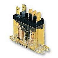
... SPDT Relays (29.7)* G2R-1-T 7.5 5.2 17.4 Five, 1.3-dia. holes 4.75 *Average value 45 max. 2.5 (43.9)* 30.5 max. SPST-NO Relays (29.7)* G2R-1A-T 7.5 17.4 Five, 1.3-dia. holes 4.75 *Average value 45 max. 2.5 (43.9)* 13 max. Terminal Arrangement/ (12.8)* Internal Connections (Bottom View) 1 ...
Page 16
... Terminal Arrangement 4 dia. holes 35.5 19.5 30 max. 54 max. Terminal Arrangement 2 4 dia. holes 35.5 19.5 30 max. 54 max. G2R Mounting Holes (for Surface Mounting) 3.2-dia. hole 39.5 0 3.5-dia. hole Mounting Holes (for Surface Mounting) (11) 3.2-dia. (12) hole (14) 39.5 0 3.5-dia. ...
Page 17
... Terminal Arrangement 14.5 max 35.5 max. 36 max. 14.5 max. 1.2 Terminal Arrangement 35.5 max. 36 max. 14.5 max. 1.2 35.5 max. 36 max. G2R Mounting Holes Tolerance: 0.1 4 Five 1.6 dia. holes 6 4 (5) 7 Mounting Holes Eight 1.3 dia. holes 7 ...
Page 18
... PFP-M 50 11.5 10M4 x 8 pan head screw Mounting Plates P2R-P 90 4.5 R2.25 10 elliptic 13.6 holes 49 42 0.1 Square hole 9 0.1 18 0.15 18 0.15 18 0.15 18 0.15 72 0.2 18 G2R Relay P2R-_A Socket PFP-100N2 7.3 0.15 4.5 27 0. Spacers PFP-S 10 6.2 1.8 1 35.5 35.3 1 ...
Page 19
... Consult OMRON for details. There is no restriction on the mounting direction of each relay on the PCB. When using this circuit, confirm the set and reset states and then take into account the circuit constant. G2R 19 ...