NF4EB-12V PANASONIC EW, NF4EB-12V Datasheet - Page 3
NF4EB-12V
Manufacturer Part Number
NF4EB-12V
Description
SIGNAL RELAY, 4PDT, 12VDC, 2A, THD
Manufacturer
PANASONIC EW
Datasheet
1.NF2EB-12V.pdf
(3 pages)
Specifications of NF4EB-12V
Contact Configuration
4PDT
Contact Current Max
2A
Contact Voltage Ac Nom
220V
Contact Voltage Dc Nom
220V
Coil Voltage Vdc Nom
12V
Coil Resistance
330ohm
Coil Power Cont
440mW
Coil Type
DC
Lead Free Status / RoHS Status
Lead free / RoHS Compliant
Available stocks
Company
Part Number
Manufacturer
Quantity
Price
Company:

Part Number:
NF4EB-12V
Manufacturer:
PANASONIC
Quantity:
879
Company:
Part Number:
NF4EB-12V
Manufacturer:
ARM
Quantity:
707
Company:
Part Number:
NF4EB-12V-1
Manufacturer:
PANASONIC
Quantity:
2 900
Company:
Part Number:
NF4EB-12V-A
Manufacturer:
PANASONIC
Quantity:
2 291


NF
REFERENCE DATA
1. Life curve
4. Contact reliability
Test conditions:
1. Contact current/voltage: 10 A 100 mV 1 kHz
2. Cycle rate 20 cps.
3. Miscontact detection level: 1 mW (= 100 )
4. Detection method: Observation of all changeover
contacts
Test result:
m = 1.5
95% confidence level = 3.1
17 contacts out of 20 achieved 10 million no miscon-
tact operations.
NOTES
1. Prevention of vibration and shock
To reduce the likelihood of vibration and
shock, we recommend that you install so
that the contact action is not in the direc-
tion of gravity.
For Cautions for Use, see Relay Technical Information.
200
= 21.2
95.0
80.0
60.0
40.0
25.0
15.0
0.15
F(t)(%)
4.0
1.5
0.4
1,000
99.9
99.0
90.0
70.0
20.0
10.0
50.0
30.0
100
5.0
3.0
2.0
1.0
0.5
0.3
0.2
0.1
10
0.1
10
Common terminal
6
Coil terminal
NO terminal
NC terminal
0.5
0.5 1.0
No. of operations, 10
1
30 V DC Resistive
Load current, A
10
1.5
5.0 10.0
6
Bottom
Top
2
6
2.5
50 100
All Rights Reserved © COPYRIGHT Matsushita Electric Works, Ltd.
2. Coil temperature rise (resistance method)
5. High temperature test
Test conditions:
Ambient temperature: 80 C 2 C
Test method:
1. All contacts were switched for 100 operations on 2
A 30 V DC resistive load.
2. Samples then were exposed to 80 C temperature
for 5,000 hours, continuous
3. Contact resistance was measured with Hewlett-
Packard testing equipment.
70
60
50
40
30
20
10
0
60
40
20
100 200 300 400 500 1,000
0.2 0.4 0.6 0.8 1.0 1.2 1.4
N.C. contacts
N.O. contacts
Operating power, W
Exposure, hrs.
3,000
5,000
Max.
Min.
Max.
Min.
3. H
Test result:
Amber relays showed a stable spread of contact resis-
tance within the initially specified 50 m after 5,000
hours exposure.
2
S gas test
500m
100m
50m
100
50
10
5
1
20 50 100 200 1,000
500
Exposure time, hrs
Sealed NFEB relay
2,000
Gas density:
Temperature: 40 C
Humidity: 90%
2 to 5 ppm
Related parts for NF4EB-12V
Image
Part Number
Description
Manufacturer
Datasheet
Request
R

Part Number:
Description:
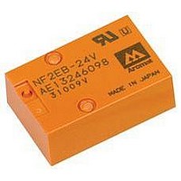
SIGNAL RELAY, 4PDT, 24VDC, 2A, THD
Manufacturer:
PANASONIC EW
Datasheet:
Part Number:
Description:
SIGNAL RELAY 4PDT 5VDC, 2A, THROUGH HOLE
Manufacturer:
PANASONIC EW
Datasheet:

Part Number:
Description:
POWER RELAY, 24VDC, 30A, SPST-NO
Manufacturer:
PANASONIC EW
Datasheet:

Part Number:
Description:
POWER RELAY, SPDT, 12VDC, 10A, PC BOARD
Manufacturer:
PANASONIC EW

Part Number:
Description:
POWER RELAY, 24VDC, 5A, SPST-NO, PCB
Manufacturer:
PANASONIC EW
Datasheet:


Part Number:
Description:
SIGNAL RELAY, DPDT, 5VDC, 2A, PC BOARD
Manufacturer:
PANASONIC EW
Datasheet:


Part Number:
Description:
PHOTOMOS RELAY, 60VDC, 400mA
Manufacturer:
PANASONIC EW
Datasheet:

Part Number:
Description:
PHOTOMOS RELAY, 400V, 150mA
Manufacturer:
PANASONIC EW
Datasheet: