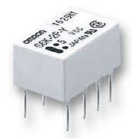
G6KU-2PY 3DC Omron, G6KU-2PY 3DC Datasheet

G6KU-2PY 3DC
Specifications of G6KU-2PY 3DC
Related parts for G6KU-2PY 3DC
G6KU-2PY 3DC Summary of contents
Page 1
... VDC G6K Single-winding Single-side stable Bellcore: latching 2, 500 V for 2x10 µs G6KU-2P-Y G6K-2P-Y G6KU-2G-Y G6K-2G-Y G6KU-2F-Y G6K-2F-Y Outside-L surface mounting terminal Inside-L surface mounting terminal PCB terminal Does not conform to Telcordia specifications UL, CSA Conforms to Telcordia specifications: 2,500 V for µs RC ...
Page 2
... The rated current and coil resistance are measured at a coil temperature of 23°C with a tolerance of ±10%. 2. The operating characteristics are measured at a coil temperature of 23°C. 3. The maximum voltage is the highest voltage that can be imposed on the relay coil instantaneously. Single-winding Latching Models (Bellcore Version) G6KU-2F-Y, G6KU-2G-Y, G6KU-2P-Y Rated voltage 3 VDC Rated current 33 Ω ...
Page 3
... Always double-check relay suitability under actual operating conditions. Single-side stable models (double-pole) G6K-2F-Y, G6K-2G-Y, G6K-2P-Y 2,500 µs), 1,500 V (10 x 160 µs) 2 (approx. 30G) 2 (approx. 20G) 2 (approx. 100G) 2 (approx. 75G) G6K Single-winding latching model G6KU-2F-Y, G6KU-2G-Y, G6KU-2P max. (approx. 1.2 ms max. (approx. 1.2 ms) 93 ...
Page 4
... Note: The tests were conducted at an ambient temperature of 23˚C. G6K Ambient Temperature vs. Switching Current Ambient temperature (°C) Ambient Temperature vs. Must Set or Must Reset Voltage G6KU-2G (F/P)-Y Max. estimated value Ambient temperature (°C) Electrical Endurance (Contact Resistance) (See note.) G6K-2G (F/P), G6K-2G (F/P)-Y NO Sample: G6K-2G ...
Page 5
... Not energized Average value Initial stage Test Sample Energized Average value (Average value) Sample: G6K-2G Must operate voltage Number of Relays: 10 Must release voltage External magnetic field (A/m) High-frequency Characteristics (Return Loss) G6K-2G (F/P),G6K-2G (F/P)-Y (Average value) 0 1.4 Sample: G6K-2G Number of Relays ...
Page 6
... Bounce Time Distribution (See note.) G6K-2G (F/P) , G6K-2G (F/P)-Y Must operate bounce time Must release bounce time Sample: G6K-2G Number of Relays: 50 Time (ms) Mounting Dimensions (Top View) Tolerance: ±0.1 mm Mounting Dimensions (Top View) Tolerance: ±0.1 mm Mounting Dimensions (Bottom View) Terminal Arrangement/ Tolerance: ±0.1 mm Eight, 0 ...
Page 7
... Note: Each value has a tolerance of ±0.3 mm. G6K-2P-Y Note: Each value has a tolerance of ±0.3 mm. G6KU-2F-Y Note: Each value has a tolerance of ±0.3 mm. G6KU-2G-Y Note: Each value has a tolerance of ±0.3 mm. G6KU-2P-Y Note: Each value has a tolerance of ±0.3 mm. Mounting Dimensions (Top View) Terminal Arrangement/ Internal Connections Tolerance: ±0.1 mm (Top View) ...
Page 8
... Industrial Association of Japan)) Reel type:RPM-16D (EIAJ) Relays per Reel: 900 1. Direction of Relay Insertion Top tape (cover tape) Carrier tape Emboss tape 2. Reel Dimensions 98 Stopper (green) 3. Carrier Tape Dimensions Pulling direction G6K-2F, G6K-2F-Y, G6KU-2F-Y Orientation mark Pulling direction G6K-2G, G6K-2G-Y, G6KU-2G-Y G6K ...
Page 9
... Time (s) • The thickness of cream solder to be applied should be within a range between 150 and 200 µm on OMRON’s recommended PCB pattern. • In order to perform correct soldering recommended that the correct soldering conditions be maintained as shown below on the left side. Correct Soldering ...
Page 10
... Be sure to adjust the level of the molten solder so that the solder will not overflow onto the PCB. Claw Securing Force During Automatic Mounting During automatic insertion of Relays, make sure to set the secur- ing force of each claw to the following so that the Relays charac- teristics will be maintained. Direction A: 1.96 N Direction B: 4.90 N Direction C: 1 ...


