G6L-1P 5DC Omron, G6L-1P 5DC Datasheet
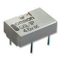
G6L-1P 5DC
Specifications of G6L-1P 5DC


Related parts for G6L-1P 5DC


G6L-1P 5DC Summary of contents
Page 1
... Contact form Rated coil voltage SPST-NO 3 VDC 4.5 VDC 5 VDC 12 VDC 24 VDC 3 VDC 4.5 VDC 5 VDC 12 VDC 24 VDC 3. Terminal shape P: PCB terminals F: Surface-mounting terminals 4. Packing state None: Stick packing TR: Tape packing G6L Model G6L-1P G6L-1F ...
Page 2
... Rated load 0 125 VAC VDC Rated carry current 1 A Max. switching voltage 125 VAC, 60 VDC Max. switching current 1 A Coil Ratings Single-side Stable Relays (G6L-1P, G6L-1F) Rated voltage 3 VDC Rated current 60.0 mA Coil resistance 50.0 Must operate voltage 75% max. of rated voltage Must release voltage 10% min ...
Page 3
... Relays to check the number of contact malfunctions. Contact Reliability Test (Contact Resistance) (See note.) 1,000 Sample: G6L-1F NO contact Number of Relays: 10 Test conditions: 1-A resistive load at 500 24-VDC with an operation rate of 50% Switching frequency: 1,800 operations/h ...
Page 4
... Frequency (MHz) G6L (Average value) + +20 + Must operate voltage Sample: G6L-1F Must release voltage Number of Relays 1,200 800 400 0 400 800 1,200 External magnetic field (A/m) High-frequency Characteristics (Return Loss, V.SWR) (Average value V.SWR 50 40 Return loss 30 20 ...
Page 5
... Each value has a tolerance of ±0.3 mm. 10.6 7 ±0.2 ±0.2 0.4 8.4 1.49 5.08 7.62 Note: Each value has a tolerance of ±0.3 mm. Vibration Resistance 5.0 Sample: G6L-1F Number of Relays: 5 4.0 3.0 2.0 1.0 Must release voltage 0.0 -1.0 Must operate voltage -2.0 -3.0 -4.0 -5.0 ...
Page 6
... R24D (Refer to EIAJ (Electronic Industries Association of Japan)) Relays per reel: 1,000 Direction of Relay Insertion Carrier tape Reel Dimensions A Carrier Tape Dimensions G6L-1F 4 ±0.1 2 ±0.1 12 ±0.1 G6L Pulling Direction Orientation mark Top tape (cover tape) Pulling direction Embossed tape 25.5 ±0.5 29.5 ±1 13 dia. ...
Page 7
... UL approval: UL60950 (File No. E41515) CSA approval: C22.2 No.60950 (File No. LR31928) Contact form Coil rating SPST-NO G6L-1P and G6L-1F VDC VDC • The thickness of cream solder to be applied should be within a range between 150 and 200 m on OMRON's recommended PCB pattern. Correct Soldering PCB Visually check that the Relay is properly soldered ...
Page 8
... G6L Precautions For general precautions, refer to the PCB Relay Catalog (X033). Familiarize yourself with the precautions and glossary before using the G6L. Correct Use Handling Leave the Relays packed until just prior to mounting them. Soldering Solder: JIS Z3282, H63A Soldering temperature: Approx. 250ºC (At 260ºC if the DWS method is used ...