G6EK-134P-ST-US-DC12 Omron, G6EK-134P-ST-US-DC12 Datasheet
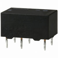
G6EK-134P-ST-US-DC12
Specifications of G6EK-134P-ST-US-DC12
Z834


Related parts for G6EK-134P-ST-US-DC12


G6EK-134P-ST-US-DC12 Summary of contents
Page 1
... Fully sealed Resistive load (p. 0. 125 VAC VDC 25 VA Model Single coil latching Dual coil latching G6EU-134P-US G6EK-134P-US G6EU-134C-US G6EK-134C-US 7. Standoff dimension Blank: 0.3 mm ST: 0. Approved Standards US: UL, CSA certified 9. Rated Coil Voltage 12, 24, 48 VDC Inductive load (p.f. = 0.4) (L ms) G6E 89 ...
Page 2
... Coil voltage current resistance (VDC) (mA) (Ω) 3 66. 125 6 33.30 180 9 22.20 405 12 16.70 720 24 8.30 2,880 Standard Dual Coil Latching Type (G6EK-134P(-ST)-US, G6EK-134C(-ST)-US) Rated Rated Coil voltage current resistance (VDC) (mA) (Ω) 3 66. 125 6 33.30 180 7 22.20 405 12 16.70 720 24 8 ...
Page 3
... Low-sensitivity Dual Coil Latching Type (G6EK-134PL(-ST)-US) Rated Rated Coil voltage current resistance (VDC) (mA) (Ω) 3 133 22.50 5 79. 66. 44.30 203 12 33.30 360 24 16.70 1,440 Note: 1. The rated current and coil resistance are measured at a coil temperature of 23°C with a tolerance of ±10%. ...
Page 4
Dimensions Note: 1. All units are in millimeters unless otherwise indicated. 2. Orientation marks are indicated as follows: Standard coil G6E-134P(L)(-ST)-US 0.6 1.6 G6E-134C(-ST)-US 3.16 2.86 0.6 1.6 Single coil latching G6EU-134P(L)(-ST)-US 0.6 1.6 G6EU-134C(-ST)-US 2.86 3.16 0.6 1.6 G6E ...
Page 5
... Dual coil latching G6EK-134P(L)(-ST)-US 0.6 1.6 G6EK-134C(-ST)-US 2.86 3.16 0.6 1.6 ■ Approvals UL Recognized (File No. E41515) / CSA Certified (File No. LR31928 Ambient Temp. = 40°C Contact form Coil ratings SPDT VDC Note: 1. The rated values approved by each of the safety standards (e.g., UL, CSA, TUV) may be different from the performance characteristics individually defined in this catalog ...
Page 6
... The relay is reset by the discharge current of C flowing in the relay via transistor TR and C. Note: 1. Give adequate consideration to the circuit constant when actually using this circuit, confirming the set and reset status of the relay. 2. OMRON owns the patent on this circuit. Consult OMRON when using this circuit. G6E 94 Low Signal Relay Wiring Refer to the following diagram when wiring to switch a DC load ...
Page 7
... Seller within 30 days of receipt of shipment. III. PRECAUTIONS 1. Suitability THE BUYER’S SOLE RESPOINSIBILITY TO ENSURE THAT ANY OMRON PRODUCT IS FIT AND SUFFICIENT FOR USE IN A MOTORIZED VEHICLE APPLICATION. BUYER SHALL BE SOLELY RESPONSIBLE FOR DETERMINING APPROPRIATENESS OF THE PARTICULAR PRODUCT WITH RESPECT TO THE BUYER’ ...
Page 8
... THE OMRON PRODUCT IS PROPERLY RATED AND INSTALLED FOR THE INTENDED USE WITHIN THE OVERALL EQUIPMENT OR SYSTEM. Complete “Terms and Conditions of Sale” for product purchase and use are on Omron’s website at http://www.components.omron.com – under the “About Us” tab, in the Legal Matters section. ...