H3CR-A8E 100-240VAC/100-125VD Omron, H3CR-A8E 100-240VAC/100-125VD Datasheet
H3CR-A8E 100-240VAC/100-125VD
Specifications of H3CR-A8E 100-240VAC/100-125VD


Related parts for H3CR-A8E 100-240VAC/100-125VD


H3CR-A8E 100-240VAC/100-125VD Summary of contents
Page 1
... H3CR-FN-300 8-pin model H3CR-A8S H3CR-F8 8-pin with H3CR-A8E H3CR-F8N instantaneous H3CR-F8-300 contact output H3CR-F8N-300 model Note: H3CR-AS, H3CR-A8S: Transistor output models Solid-state Timer H3CR H3CR H3CR H3CR Common to ALL Timers Operation . . . . . . . . . . . . . . . . . . . . . . . . . . . . . . . . . . . . . . . . . . . . . . . . . . . . . . . . . . ...
Page 2
... A wider power supply range reduces the number of timer models kept in stock. A wide range of applications through six or four operating modes. Reduced power consumption. (Except for H3CR-A8E) Enables easy sequence checks through instanta- neous outputs for a zero set value at any time range. Length, when panel-mounted with a Socket less ...
Page 3
... VDC contact VDC/VAC (50/60 Hz) Note: 1. Specify both the model number and supply voltage when ordering. Example: H3CR-A 100 to 240 VAC (50/60 Hz)/100 to 125 VDC 2. The operating modes are as follows A: ON-delay B: Flicker OFF start B2: Flicker ON start C: Signal ON/OFF-delay Model Number Legend: ...
Page 4
... Item H3CR-A/-AS Operating mode A: ON-delay B: Flicker OFF start B2: Flicker ON start C: Signal ON/OFF-delay D: Signal OFF-delay E: Interval G: Signal ON/OFF-delay (Only for H3CR-A-300) J: One-shot (Only for H3CR-A-300) Pin type 11-pin Input type No-voltage input Time-limit output H3CR-A/-A8/-AP: Relay output (DPDT) type H3CR-AS/-A8S: Transistor output (NPN/PNP universal)* ...
Page 5
... VAC (50/60 Hz)/100 to 125 VDC VAC (50/60 Hz)/ VDC ( VAC/VDC for H3CR-A8E) (see note 2) 85% to 110% of rated supply voltage (90% to 110 VDC) Minimum power-opening time: 0.1 s No-voltage Input ON impedance: 1 kΩ max. ...
Page 6
... Immunity Surge: Case color Light gray (Munsell 5Y7/1) Degree of protection IP40 (panel surface) Weight Approx Note: The value is ±5% FS +100 ms to –0 ms max. when the mode signal of the H3CR-AP is OFF. 8 0.05 s (H3CR-A/-AS times each in 6 directions 2 3 times each in 6 directions ...
Page 7
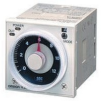
... Reference: A maximum current of 0.15 A can be switched at 125 VDC (cosφ and a maximum current of 0.1 A can be switched if L ms. In both cases, a life of 100,000 operations can be expected. The minimum applicable load (100 mA for H3CR-A8E VDC (failure level: P). Operating mode display window Operating mode selector ...
Page 8
... Start 10 Zero setting detection circuit Oscillation Power supply circuit circuit Zero setting detection circuit Oscillation Power supply circuit circuit H3CR-A Time range/ Operating unit selectors mode selector Counting Output circuit circuit Indicator Input circuit circuit Power-ON Output-ON indicator indicator Time range/ ...
Page 9
... OFF while the reset input is ON. Gate Prohibits time-measurement. Outputs Control output Outputs are turned ON according to designated output mode when preset value is reached. Note: H3CR-AP incorporates start input only. Zero setting Time range/ detection unit selectors circuit Oscillation ...
Page 10
... Note: 1. The minimum power-opening time (“Rt”) is 0.1 s and the minimum pulse width is 0. The letter “t” in the timing charts stands for the set time and “t–a” means that the period is less than the time set. H3CR-A/-AS/-AP* *H3CR-AP model incorporates start input only. Operating mode ...
Page 11
... Gate OFF ON Reset OFF ON Output relay OFF Note: 1. This timing chart indicates the gate input in op- erating mode A (ON-delay operation). 2. The set time is the sum H3CR-AP model incorporates start input only. Timing chart 1±0.6 s (Fixed) and H3CR-A Basic operation Power Start ...
Page 12
... Power indicator J: One-shot output Power Output relay (NC) 1±0.6 s Output relay (Fixed) (NO) (output indicator) Power indicator 14 Timing chart Basic operation Power t Output Basic operation Power t Output Basic operation Power t Output Basic operation 1±0.6 s Power (Fixed) Output H3CR 1±0.6 s (Fixed) ...
Page 13
... Power indicator J: One-shot Power output Output relay (NC) Output relay (NO) (output indicator) Instantaneous output relay (NC) Instantaneous output relay (NO) Power indicator Timing chart (Fixed) (Fixed) H3CR-A Basic operation Power t Output Basic operation Power Output Basic operation Power t Output Basic operation Power t 1± ...
Page 14
... These dimensions vary with the kind of DIN track (reference value dia dia dia. 50 Time Setting Ring Dimensions with Back Connecting Socket P3G-08/P3GA-11 81 H3CR-A8j H3CR-A 87.6 H3CR-AS + Adapter P3GA-11 Y92F-30 P2CF-08 Y92A-48G * 2.3 P2CF-08-E H3CR-A 66.6 52.3 0.7 44.8 x 44.8 11 pins 66.6 6 52.3 ...
Page 15
... H3CR-A Installation Terminal Arrangement Note: The delayed contact of conventional Timers was indicated as The contact symbol of the H3CR-A is indicated as H3CR-A8). 11-pin Models H3CR-A (Contact Output) (–)(~) Power supply H3CR-AS (Transistor Output) (–)(~) Power supply Note: Terminals and 8 are empty. Terminals and 10 are the same as for the H3CR-A. ...
Page 16
... H3CR-A Input Connections H3CR-A/-AS The inputs of the H3CR-A/-AS are no-voltage (short-circuit or open) inputs. No-voltage Inputs No-contact Input (Connection to NPN open collector output sensor VDC (sensor power supply power – supply Timer Sensor 5 Gate 6 Start 7 Reset 2 Input (0 V) Operates with transistor ON No-voltage Input Signal Levels No-contact 1 ...
Page 17
... H3CR-A H3CR-AP The start input of the H3CR-AP is voltage input. (Voltage imposition or open) Voltage Inputs No-contact Input (Connection to PNP open collector output sensor VDC (sensor power supply power supply – Sensor Timer 10 Power supply (+) 6 Start 7 Input 0V 2 Power supply (–) Operates with PNP transistor ON ...
Page 18
... OFF) alarms or the monitoring of an intermittent operation with a display. 1. Power-ON Start/Power-OFF Reset (in B Mode) Power (2 and 10) Start (2 and 6) Control output and 11 and 4) Lit Control output and 11 and 3) Power indicator Externally short-circuited H3CR set time Flashing Lit Power ...
Page 19
... OFF. 1. Power-ON Start/Instantaneous Operation/Time-limit Reset Power (2 and 10) Start (2 and 6) Control output and 11 and 4) Control output and 11 and 3) Power indicator Start signal (NC to NO) H3CR-A Power supply (Power continuously supplied) Lit Flashing Lit Power supply 21 ...
Page 20
... This function is useful for the repetitive control such as the filling of liquid for a specified period after each Signal start input. Power (2 and 10) Start (2 and 6) Control output and 11 and 4) Control output and 11 and 3) Flashing Lit Start signal H3CR Power supply (Power continuously supplied) ...
Page 21
... VAC 24 VAC/DC 12 VDC 48 to 125 VDC Flicker ON start 100 to 240 VAC 24 VAC/DC 12 VDC 48 to 125 VDC Note: Specify both the model number and supply voltage when ordering. Example: H3CR-F 24 VAC/DC Supply voltage Model Number Legend: H3CR - - Classification F: Twin timers 2 ...
Page 22
... For PL08 and PL11 Sockets Y92H-7 For PF085A Socket Y92H-8 H3CR-F8 8-pin x10 s ( 0. 120 1 300 x10 min (10 min) 1 0. 120 1 300 H3CR-F Models H3CR-FN H3CR-F8N Flicker ON start 11-pin 8-pin min h (hrs) h (hrs) x10 h ( 120 30 to 300 ...
Page 23
... EN61812-1 EN55011 Group 1 class A EN55011 Group 1 class A EN61812-1 IEC61000-4-2: IEC61000-4-4: IEC61000-4-5: H3CR contact discharge (level air discharge (level 3) IEC61000-4-3:10 V/m (80 MHz to 1 GHz) (level (0. MHz) (level power-line (level I/O signal-line (level line to line 2 kV line to ground (level 3) ...
Page 24
... RAM Clock One-chip microcomputer --- Outputs are turned ON/OFF according to the time set by the ON- and OFF-time setting knob. H3CR-F OFF-time unit display window OFF-time unit selector (select one from sec min., and hrs, or from min, hrs, and 10 h) ON-time setting knob (with orange pointer) ...
Page 25
... When power is supplied in flicker ON start mode, the OFF indicator lights momentarily. This, however, has no effect on the perfor- mance of the Timer. Timing chart ON OFF OFF ON OFF ON Lit Not lit Lit Not lit ON OFF ON OFF ON OFF OFF ON OFF Lit Not lit Lit Not lit ON OFF ON OFF H3CR-F 0.1 s min OFF OFF 0.1 s min OFF 27 ...
Page 26
... Power supply dia dia dia dia. Dimensions with Back Connecting Socket P3G-08/P3GA-11 81.5 17.4 80 H3CR-F8 H3CR-F8N 90.0 H3CR-F H3CR-FN P3GA-11 Y92F-30 (When P2CF-08 * Y92A-48G 2.3 P2CF-08-E mounted) H3CR-F H3CR-FN H3CR-F-300 H3CR-FN-300 (+) (~) (–)(~) Note: Leave terminals 5, 6, and 7 open. Do not use them as relay terminals. ...
Page 27
... A wide star-time range (up to 120 seconds) and star-delta transfer time range (up to 0.5 seconds). Ordering Information Outputs Time-limit contact Time-limit contact and instantaneous contact Note: Specify both the model number and supply voltage when ordering. Example: H3CR-G8L 100 to 120 VAC Supply voltage Model Number Legend: H3CR - ...
Page 28
... Black (N1.5) Y92P-48GB Medium gray (5Y5/1) Y92P-48GM For PL08 and PL11 Sockets Y92H-1 For PF085A Socket Y92H-2 H3CR-G8L SPST-NO (delta operation circuit) H3CR-G Models H3CR-G8EL Star-delta timer with instantaneous output Time-limit: SPST-NO (star operation circuit) SPST-NO (delta operation circuit) Instantaneous: SPST-NO ...
Page 29
... Case color Light Gray (Munsell 5Y7/1) Enclosure ratings IP40 (panel surface) Weight H3CR-G8L: approx. 110 g; H3CR-G8EL: approx. 130 g 100 to 120 VAC (50/60 Hz), 200 to 240 VAC (50/60 Hz) 85% to 110% of rated supply voltage Minimum power-opening time: 0.5 s 100 to 120 VAC: approx (2 120 VAC 200 to 240 VAC: approx (3 240 VAC Contact output 250 VAC/30 VDC, resistive load (cosφ ...
Page 30
... The minimum applicable load VDC (failure level: P). Time unit display (sec is fixed) Time setting knob (for setting star operation time) Star-delta transfer time selector (select one from 0.05 s, 0.1 s, 0.25 s, and 0.5 s) Star-delta transfer time display window H3CR-G ...
Page 31
... If the time reaches the value set with the time setting knob, the star operation output will be turned OFF and there will be delta operation output after the set star-delta transfer time has elapsed. H3CR-G Star-delta transfer time Star operation counting Output ...
Page 32
... Star-delta transfer time Model H3CR-G8L/-G8EL Power (2 – 7) Instantaneous output (1 – 3) (-E models) Star operation output (8 – 5) Delta operation output (8 – 6) Star operation indicator Delta operation indicator 34 Timing chart ON OFF ON OFF OFF ON OFF Lit Not lit Lit Not lit H3CR-G 0.5 s min. ...
Page 33
... Time setting ring Panel cover Dimensions with Back Connecting Socket P3G- 2.3 H3CR-G8EL Star operation Instantaneous contact contact ( ~ ) Note: Leave terminal 4 open. Do not use H3CR-G 78.0 0.7 44.8 x 44.8 8 pins 92.9 86.4 H3CR- G8jL P3G-08 Y92F-30 (When Y92A-48G mounted) Delta Star ...
Page 34
... Ordering Information Input Output --- DPDT With reset input SPDT Note: Specify both the supply voltage and time unit code ( addition to the model number when ordering. Example: H3CR-H8L 24 VAC/DC M Model Number Legend: H3CR - Classification H: Power OFF-delay timer 2 ...
Page 35
... Time Ranges Time unit Setting 0.6 1 Min. power ON time Note: If the above minimum power ON time is not secured, the H3CR may not operate. Be sure to secure the above minimum power ON time. Y92F-30 Y92F-70 Y92F-71 PFP-50N 50 cm (l) x 7 (l) x 7.3 mm (t) PFP-100N (t) ...
Page 36
... EN61812-1 EN55011 Group 1 class A EN55011 Group 1 class A EN61812-1 IEC61000-4-2: IEC61000-4-4: IEC61000-4-5: H3CR contact discharge (level air discharge (level 3) IEC61000-4-3:10 V/m (80 MHz to 1 GHz) (level (0. MHz) (level power-line (level I/O signal-line (level line to line 2 kV line to ground (level 3) ...
Page 37
... A can be switched if L ms. In both cases, a life of 100,000 operations can be expected. The minimum applicable load VDC (failure level: P). Output indicator (red) Scale range display windows Time setting knob (for setting power OFF-delay time) Time unit display S-series: sec M-series: min H3CR-H 39 ...
Page 38
... H3CR-H Operation Block Diagrams Without Reset Input (H3CR-H8L) Power supply AC (DC) input circuit Power failure detection circuit With Reset Input (H3CR-H8RL/-HRL) Power supply AC (DC) input circuit Power failure detection circuit Reset input I/O Functions Inputs Reset Outputs Control output 40 Time range ...
Page 39
... Note: If the power is turned ON until the set time is up, the timer will be retriggered. Timing chart OFF Lit Not lit OFF 0.05 s min. ON (Short-circuited) OFF (Open) Lit Not lit Rt ON OFF 0.05 s min. Lit Not lit H3CR 0.05 s min 0.05 s min. 41 ...
Page 40
... These dimensions vary with the kind of DIN track (reference value dia dia. Dimensions with Back Connecting Socket P3G-08/P3GA-11 92.9 15 86.4 H3CR-HRL 109.9 H3CR- H8jL Y92F-30 P2CF-11 * 2.3 P2CF-11-E H3CR-H 78.0 63.7 0.7 44.8 x 44.8 8 pins 78.0 63.7 0.7 44.8 x 44.8 11 pins 92 ...
Page 41
... Power supply 11-pin Model With Reset Input (H3CR-HRL) Reset input (–)(~) (+)(~) Power supply Note: Leave terminal 6 open. Do not use them as relay terminals. With Reset Input (H3CR-H8RL) Reset input (–) (+) (~) (~) Power supply Note: Leave terminal 3 open. Do not use them as relay terminals. ...
Page 42
... A time range (1.2, 3, 12, or 30/2. for H3CR-Aj-301) is selected with the time range selector at the lower left corner of the front panel, and the selected time range appears (in the window at the lower right part) within the plastic frame of the time setting knob ...
Page 43
... Star operation time range selector The time required for switching (0.05, 0.1, 0.25, or 0.5 second) from the star operation to the delta operation of the H3CR-G can be se- lected with the star-delta transfer time selector at the lower right cor- ner of the front panel. ...
Page 44
... Note: All units are in millimeters unless otherwise indicated. Flush Mounting Adaptor Y92F-30 Note: The adapters for two or more timers mounted in a vertical line are different in orientation from those mounted in a horizontal line. N can be obtained as follows (n: the number of H3CR models arranged side by side) +1 Without a Cover (48n - 2. With the Protective Cover (51n - 5 ...
Page 45
... Terminal Arrangement/ Internal Connections 35.4 (Top View) Two, 4.5 dia. holes 31.2 max. 5 4.5 7.8 3 1.2 35.4 Two, 4.5 dia. holes 30 31.2 max. H3CR Surface Mounting Holes Two, 4.5 dia. or two, M4 40±0.2 Surface Mounting Holes Two, 4.5 dia. or two, M4 40±0.2 47 ...
Page 46
... View) 25.6 4.5 6.2 16.3 Twelve, 6.4 dia. holes 34 47.7 x 47.7 16.5 47.4 PFP-100N2 7.3±0.15 4.5 27±0.15 35±0 ( (see note) Spacer PFP-S 10 6.2 1.8 1 35.5 35.3 1.8 1.3 4.8 H3CR 24.6 27 35±0 1,000 34.8 44.3 16.5 29.2 1.5 ...
Page 47
... The Protective Cover cannot be mounted if the Panel Cover (sold separately) is used on the Timer. Y92A-48B Time Setting Ring/Panel Cover for H3CR-A/-G There are three types of Panel Covers (Y92P-48GL, Y92P-48GB, and Y92P-48GM), all of which are available in three colors. Use the most suitable type of Panel Cover with the design of the scaling plate according to the application ...
Page 48
... Make sure that no voltage is applied to any terminals before dis- mounting the Timer from the Socket. The output section of the H3CR is provided only with basic isolation. The H3CR itself is designed under the following conditions: • ...
Page 49
... Precautions (H3CR-A) Note: The undermentioned is common for all H3CR-A models. Power Supplies For the power supply of an input device of the H3CR-Aj/-AjS/-AP, use an isolating transformer with the primary and secondary wind- ings mutually isolated and the secondary winding not grounded. Example: H3CR-A ...
Page 50
... H3CR-A 2 Common to All H3CR-A Models With the H3CR-AP, input wires must be as short as possible. If the floating capacity of wires exceeds 1,200 pF (approx for cables with 120 pF/m), the operation will be affected. Pay particular atten- tion when using shielded cables. The H3CR-AjS transistor output is isolated from the internal cir- cuitry by a photocoupler ...
Page 51
... Output Short-circuit current required that the output be turned on repeatedly with an inter- val of shorter than 3 s, consider use of the H3CR-A in mode D (sig- nal OFF-delay). Others If the H3CR-H is dropped or experiences some other kind of shock, because a latching relay is used for output, contacts may be reversed or go into a neutral state ...
Page 52
... H3CR 54 H3CR ...
Page 53
... H3CR H3CR 55 ...
Page 54
... To convert millimeters into inches, multiply by 0.03937. To convert grams into ounces, multiply by 0.03527. Cat. No. L084-E1-04 In the interest of product improvement, specifications are subject to change without prior notice. OMRON Corporation Industrial Automation Company Industrial Control Components Division Shiokoji Horikawa, Shimogyo-ku, Kyoto, 600-8530 Japan Tel: (81)75-344-7119/Fax: (81)75-344-7149 56 H3CR Printed in Japan 0202-1M (0696) (A) ...