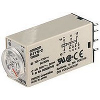
H3YN-21 100-120VAC Omron, H3YN-21 100-120VAC Datasheet

H3YN-21 100-120VAC
Specifications of H3YN-21 100-120VAC
Related parts for H3YN-21 100-120VAC
H3YN-21 100-120VAC Summary of contents
Page 1
... Note: 1. Sockets and Hold-down Clips are not included with the H3YN. They must be ordered separately. 2. Only models with 24-VDC power supply are available. 3. Use the H3YN-4 or H3YN-41 Series when switching micro loads, and use the H3YN-4-Z or H3YN-41-Z Series when switching even smaller loads. ...
Page 2
... Note not use the output from an inverter as the power supply. Refer to Safety Precautions for All Times for details. 2. Single-phase, full-wave-rectified power supplies can be used. 3. When using the H3YN continuously in any place where the ambient temperature range of 45°C to 50°C, supply 90% to 110% of the rated supply voltages (supply 95% to 110% with 12 VDC type). ...
Page 3
... Immunity RF-interference from AM Radio Waves: Immunity Burst: Immunity Surge: Approved standards UL508, CSA C22.2 No. 14, Lloyds Conforms to EN61812-1 and IEC60664-1. (2.5 kV/2 for H3YN-2/-21, 2.5 kV/1 for H3YN-4/-41, H3YN- 4-Z/-41-Z) Output category according to EN60947-5-1. Note: 1. Terminal screw sections are excluded. 2. Refer to the Life-test Curve. ...
Page 4
... Maximum current of 0.2 A can be switched if L ms. In both cases, a life of 100,000 operations can be expected. The minimum applicable load is 0 VDC (P reference value). 250 VAC, cosφ = 0.4 5,000 24 VDC, L 1,000 500 200 Load current (A) 250 VAC, cosφ = 0.4 5,000 24 VDC, L 1,000 500 200 Load current (A) H3YN 4 ...
Page 5
... Connection H3YN-2/-21 DIN Indication Timer circuit UP PW Pulse Operation A pulse output for a certain period can be obtained with a random external input signal. Use the H3YN in interval mode as shown in the following timing charts. H3YN-2/-21 Timer circuit External input H3YN-4/-41 H3YN-4-Z/-41-Z Timer ...
Page 6
... Power (13-14) Time limit contact NC (9-1, 10-2, 11-3, 12-4) Time limit contact NO (9-5, 10-6, 11-7, 12-8) Run/Power indicator (PW) Output indicator (UP) Power (13-14) Time limit contact NC (9-1, 10-2, 11-3, 12-4) Time limit contact NO (9-5, 10-6, 11-7, 12-8) Run/Power indicator (PW) Output indicator (UP) H3YN H3YN-4/-41 6 ...
Page 7
... DIP Switch Settings The 1-s range and ON-delay mode for H3YN-2/-4/-4-Z, the 1-min range and ON-delay mode for H3YN-21/-41/-41-Z are factory-set before shipping. Time Ranges Model Time range Time setting range H3YN- 0 H3YN-4 H3YN-4 min 0 min 10 min min ...
Page 8
... Mounting Height PY08 (PY14 (see note)) PYF08A/PYF08A-N/PYF08A-E (PYF14A/PYF14A-N/PYF14A-E (see note)) H3YN Series PYF08A (PYF14A) Note: Models in parentheses are Connecting Sockets to the H3YN-4/-41 or H3YN-4-Z/-41-Z. Eight, 3 × 1.2 elliptic holes 28 max. 6.4 21.5 max. (63.0) Fourteen, 3 × 1.2 elliptic holes 28 max. ...
Page 9
... Accessories (Order Separately) Connecting Sockets Use the PYF@A, PY@, PY@-02, or PY@QN(2) to mount the H3YN. When ordering any one of these Sockets, replace “@” with “08” or “14.” Track Mounting/Front Connecting Sockets PYF08A Two, 4.2 × 5 3.4 6 mounting holes Eight, M3 × ...
Page 10
... View) Panel Cutout Terminal Arrangement (Bottom View) 25.8 PY08 PY14 Terminal Arrangement (Bottom View) PY08QN PY14QN PY08QN(2) PY14QN(2) Terminal Arrangement (Bottom View) PY08@-02 PY14@-02 H3YN Two, 4.5 dia Two, 4.5 dia +0.2 21.4 0 H3YN 59.3 Series +0.2 0 PY@, PY@-02, PY@QN(2) 10 ...
Page 11
... PYP-1 Two, 3.4-dia. holes 1.6 Square hole Hold-down Clips The Hold-down Clip makes it possible to mount the H3YN securely and prevent the H3YN from falling out due to vibration or shock. Y92H-3 Y92H-4 3 48.5 25.1 33.5 Note: 1. Push the H3Y in until the Adaptor (Y92F-78) ...
Page 12
... H3YN and an auxiliary relay, such Relay, in combination. : Auxiliary relay such as MY Relay In the case of the above circuit, the H3YN will be in pulse operation. Therefore, if the circuit shown on page 5 is used, no auxiliary relay will be required. Do not set to the minimum setting in the flicker modes, otherwise the contact may become damaged ...
Page 13
... Please read and understand this catalog before purchasing the products. Please consult your OMRON representative if you have any questions or comments. WARRANTY OMRON's exclusive warranty is that the products are free from defects in materials and workmanship for a period of one year (or other period if specified) from date of sale by OMRON. OMRON MAKES NO WARRANTY OR REPRESENTATION, EXPRESS OR IMPLIED, REGARDING NON-INFRINGEMENT, MERCHANTABILITY, OR FITNESS FOR PARTICULAR PURPOSE OF THE PRODUCTS ...


