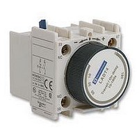
LADT4 TELEMECANIQUE, LADT4 Datasheet

LADT4
Specifications of LADT4
Related parts for LADT4
LADT4 Summary of contents
Page 1
Characteristics Type of contactor Environment Rated insulation voltage (Ui) Conforming to EN 60947-4-1, overvoltage category III, degree of pollution: 3 Conforming to UL, CSA Rated impulse withstand voltage Conforming to EN 60947 (Uimp) Conforming to standards Product certifications Separation insulation ...
Page 2
Characteristics Type of contactor LC1- Power circuit connections Connection via cable Tightening Flexible cable 1 conductor mm 2 without cable end 2 conductors mm 2 Flexible cable 1 conductor mm 2 with cable end 2 conductors mm 2 Solid cable ...
Page 3
Characteristics Type of contactor Pole characteristics Rated operational current (Ie) In AC-3, (Ue 440 V) In AC-1, Rated operational voltage (Ue Frequency limits Of the operating current Conventional thermal current (Ith) 60 °C Rated making capacity (440 V) ...
Page 4
D32 DT60 D38 D40 690 690 690 1000 25…400 25…400 25…400 25…400 550 500 550 800 550 500 550 800 430 430 430 720 260 260 310 320 ...
Page 5
Characteristics (continued) d.c. control circuit characteristics Type of contactor $ Rated control circuit voltage (Uc) Rated insulation voltage Conforming to IEC 947-1 Conforming to UL, CSA Control voltage limits Operational Drop-out $ Average consumption at 20 °C and at Uc ...
Page 6
Characteristics (continued) Contactor integral auxiliary contact characteristics Linked contacts conforming to Each contactor has 2 N/O and N/C contacts mechanically linked on the same movable contact holder draft standard IEC 947-4-5 Mirror contact The N/C contact on each contactor represents ...
Page 7
... Without derating Cabling Phillips N° 2 and Ø Flexible or solid cable with or without cable end Connection by spring terminals Flexible or solid cable without cable end Instantaneous and time delay contact characteristics Number of contacts Rated operational voltage (Ue Rated insulation voltage (Ui) Conforming to EN 60947-5-1 Conforming to UL, CSA ...
Page 8
Characteristics Contact block type Environment Conforming to standards Product certifications Protective treatment Conforming to IEC 68 Degree of protection Conforming to VDE 0106 Ambient air temperature Storage and operation Cabling Phillips N° 2 and Ø Flexible or solid ...
Page 9
Characteristics Operational power of contacts a.c. supply, categories AC-14 and AC-15 Electrical durability (valid up to 3600 operating cycles/hour inductive load such as the coil of an electromagnet: making power (cos 1 million operating cycles 3 million operating ...
Page 10
Characteristics Environment Conforming to standards Product certifications Protective treatment Conforming to IEC 68 Degree of protection Conforming to VDE 0106 Ambient air temperature Storage around the device Operation Permissible for operation at Uc “Auto - Man - Stop” control modules ...
Page 11
... V 0.8…1 mechanical contact only s 0.1…2; 1.5…30; 25…500 ± (10 ms minimum) ms 150 – Illuminates during time delay period < 3.3 3 kV; 0.5 joule 30 LA4-DR “Off-delay” electronic timers U supply (A1-A2) Control (A2-B2) Time delay output Contactor coil Red LED ...
Page 12
Characteristics Environment Conforming to standards Product certifications Protective treatment Conforming to IEC 68 Degree of protection Conforming to VDE 0106 Ambient air temperature Storage around the device Operation Permissible for operation at Uc Other characteristics Module type Rated insulation voltage ...


