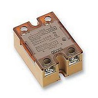
G3NA-240B 5-24DC Omron, G3NA-240B 5-24DC Datasheet

G3NA-240B 5-24DC
Specifications of G3NA-240B 5-24DC
Related parts for G3NA-240B 5-24DC
G3NA-240B 5-24DC Summary of contents
Page 1
... Phototriac Yes Photocoupler o ocou e Phototriac Photocoupler o ocou e *Loss time increases under 75 VAC. (Refer to page 148.) Note: When ordering a TÜV-approved model, add “-UTU” to the model number as shown below: Example: G3NA-210B-UTU Indicator Rated output load (Applicable output load 240 VAC ...
Page 2
... OMRON’s heat sink (refer to the accessories heat sink of specified size is used. 2 Low-cost Models Model Y92B-A100 Y92B-A150N Y92B-A250 Mounting Bracket Used to mount the G3NA with a mounting dimension of 56 mm. Model R99-11 See Dimensions for details. (Refer to page 148.) Operating voltage Impedance VDC 7 mA max.* ...
Page 3
... Operating: 45% to 85% Weight Approx G3NA-240B 1.8 V (RMS) max max. (at 200 VAC max. (at 400 VAC) 2 – 100 C (with no icing or condensation) Approx Approx G3NA-410B, -420B, G3NA-D210B -440B, -450B 1 ms max. (DC input max. (AC input max. (DC input max. (AC input) 1.5 V max max. (at 200 VDC) Approx G3NA ...
Page 4
... Y92B-N150) 20 With iron plate measuring 100 x 100 x 0 Without heat sink Ambient temperature ( C) G3NA G3NA-220B/420B With standard heat sink (Y92B-A100 or Y92B-N100) or alumi- num plate measuring 200 mm x 200 With iron plate measuring 100 x 100 x 0 Without heat sink Ambient temperature ( C) ...
Page 5
... For example, when a current allowed to flow through the SSR the graph shows that the heat sink 2 size is about 450 cm . Therefore, if the heat sink is square, one side of the heat sink must (15 G3NA G3NA-220B/420B Energizing time (ms) Temperature Characteristics (with Must Operate Voltage and Must Release Voltage) ...
Page 6
... In the case of surface mounting, a 30% derating of the load current is required. The orientation indicated by the external dimensions is not the correct mounting orientation. When opening mounting holes, refer to the mount- ing hole dimensions. G3NA-205B, G3NA-210B, G3NA-220B, G3NA-410B, G3NA-420B 58 max. 47.5 44 G3NA-240B, G3NA-440B, G3NA-450B 58 min ...
Page 7
... Y92B-A250 Three, M4 holes 47.6 R2.2 50 0.1 56 0.5 150 max. Four, M4 190.5 max. 130.5 max. 70 max. G3NA Mounting Holes 35 0.2 75 max. Two, 4.4-dia holes 90 0.4 13 4.5 Weight: approx. 400 g Mounting Holes 35 0.2 Two, 4.4-dia. 104 max holes 90 0 ...
Page 8
... Input Recommended Capacitor: Nissei Denki’s MKT-series R40 (1 F) The output terminal side of the G3NA-D210B is connected to a built- in diode for protecting the SSR from damage that may result from reverse connection. The SSR, however, cannot withstand one min- ute or more if the wires are connected in reverse order. Therefore, pay the utmost attention not to make polarity mistakes on the load side ...


