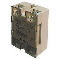
G3NA-290B-UTU-AC100-240 Omron, G3NA-290B-UTU-AC100-240 Datasheet

G3NA-290B-UTU-AC100-240
Specifications of G3NA-290B-UTU-AC100-240
Related parts for G3NA-290B-UTU-AC100-240
G3NA-290B-UTU-AC100-240 Summary of contents
Page 1
... Wide Lineup of General-purpose Solid State Relays with Applicable Loads • AC Output Relays with 75-A and 90-A output currents have been added to the G3NA Series. The standard versions of these models provide certification for international standards (-UTU). • All models feature the same compact dimensions to provide a uniform mounting pitch. • ...
Page 2
... Refer to Load Current vs. Ambient Temperature in Engineering Data on page 5. 2. Loss time increases under 75 VAC. (Refer to page 14.) Confirm operation with the actual load. ■ Accessories (Order Separately) One-touch Mounting Plates Model R99-12 FOR G3NA Heat Sinks Slim Models Enabling DIN-track Mounting Model Applicable SSR ...
Page 3
... Note: 1. The input impedance is measured at the maximum value of the rated supply voltage (for example, with the model rated at 100 to 120 VAC, the input impedance is measured at 120 VAC). 2. With constant current input circuit system. The impedance for the G3NA-2@@B-UTU max. 3. Refer to Temperature Characteristics (for Must Operate Voltage and Must Release Voltage) in Engineering Data on page 6 for further details ...
Page 4
... G3NA- G3NA- G3NA- 240B 410B 420B 440B 450B 1.8 V (RMS) max max. (at 200 VAC max. (at 400 VAC) Approx. Approx G3NA G3NA- G3NA- G3NA- G3NA- D210B 275B- 290B- 475B- UTU UTU UTU 1 ms 1/2 of load power source cycle + 1 ms max. (DC max. (DC input) ...
Page 5
... Without heat sink 0 − − 100 Ambient temperature (°C) G3NA G3NA-220B/420B With standard heat sink (Y92B-A100 or Y92B-N100) or aluminum plate measuring 200 mm x 200 With iron plate measuring 100 x 100 x t0 Without heat sink Ambient temperature (°C) G3NA-450B 60 50 With standard heat sink ...
Page 6
... Energized time (ms) Temperature Characteristics (for Must Operate Voltage and Must Heat Sink Area Release Voltage) vs. Load Current G3NA-220B G3NA-2@@B AC input 3,000 40 2,000 Ambient temperature 80°C 1,000 20 700 500 300 0 200 100 70 − −40 −30 − ...
Page 7
... Dimensions ■ Relays Note: All units are in millimeters unless otherwise indicated. G3NA-205B, G3NA-210B, G3NA-220B 58 max. 47.5 44 G3NA-240B, G3NA-275B-UTU, G3NA-475B-UTU G3NA-440B, G3NA-290B-UTU, G3NA-490B-UTU 58 min. 47.5 44 G3NA-D210B Note: The load can be connected to either the positive or negative side. 58 max. 47.5 44 G3NA-410B, G3NA-420B 58 max. 47 ...
Page 8
... Heat Sinks Y92B-N50 Heat Sink (for the G3NA-205B, G3NA-210B, G3NA-D210B, G3NA-410B, G3NE-210T(L)) For surface mounting, a 30% derating of the load current is required (from the Load Current vs. Ambient Temperature graphs). The orientation indicated by the external dimensions is not the correct mounting orientation. When opening mounting holes, refer to the mounting hole dimensions ...
Page 9
... Y92B-P250NF Heat Sink (for the G3NA-275B-UTU, G3NA-475B-UTU, G3NA-290B-UTU, G3NA-490B-UTU) The orientation indicated by the external dimensions is not the correct mounting orientation. When opening mounting holes, refer to the mounting hole dimensions. Observe the precautions given in Mounting Method under Precautions for Correct Use. ...
Page 10
... Y92B-P250 Two, M4 Four, M4 Depth 10 47.6 Four, R2.5 130.5 max. Y92B-A100 Heat Sink (for the G3NA-205B, G3NA-210B, Y92B-A150N Heat Sink G3NA-220B, (for the G3NA-240B, G3NA-410B, G3NA-440B) G3NA-420B, G3NA-D210B) Three, M4 holes Two, M4 holes R2.2 47.6 50±0.1 100 max. Weight: approx. 210 g Weight: approx. 310 g ...
Page 11
... Do not use the G3NA if the heat sink fins are bent, e.g., as the result of dropping the G3NA. Heat dissipation characteristics will be reduced, possibly causing G3NA failure. ...
Page 12
... Operating and Storage Locations Do not use or store the G3NA in the following locations. Doing so may result in damage, malfunction, or deterioration of performance characteristics. • Do not use or store in locations subject to direct sunlight. • Do not use in locations subject to ambient temperatures outside the range –20 to 60°C. ...
Page 13
... Refer to the following table for the OMRON Fan power supply plug cables (order separately). Cable UL certified length 1 m R87F- R87F-PC-20 • Connect the ground screw hole on the fan to PE. G3NA 200 V 85% to 110% of rated voltage 50/60 Hz 0.061 0.052 2,600 r/min 3,050 r/min 240 VAC, resistive load VDC, resistive load ...
Page 14
... Input G3NA-UTU • The input cable must be less than 3 m. Loss Time The loss time will increase when the G3NA is used at a low applied voltage or current. Be sure that this does not cause any problems. Using DC Loads For load, a diode should be connected in parallel the load to absorb the counter electromotive force of the load ...
Page 15
... G3NA in locations or by means that will subject it to vibration from other devices, such as motors. 4. Solvents Do not allow the G3NA or the resin portion of the Fan’s thermostat to come in contact with solvents, such as thinners or gasoline. Doing so will dissolve the markings on the G3NA. 5. Oil Do not allow the G3NA terminal cover to come in contact with oil ...
Page 16
... Please read and understand this catalog before purchasing the products. Please consult your OMRON representative if you have any questions or comments. WARRANTY OMRON's exclusive warranty is that the products are free from defects in materials and workmanship for a period of one year (or other period if specified) from date of sale by OMRON. OMRON MAKES NO WARRANTY OR REPRESENTATION, EXPRESS OR IMPLIED, REGARDING NON-INFRINGEMENT, MERCHANTABILITY, OR FITNESS FOR PARTICULAR PURPOSE OF THE PRODUCTS ...


