ZBZ1604 SQUARE D, ZBZ1604 Datasheet - Page 61
ZBZ1604
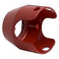
Manufacturer Part Number
ZBZ1604
Description
Switch Guard
Manufacturer
SQUARE D
Datasheet
1.ZBZ1604.pdf
(240 pages)
Specifications of ZBZ1604
Features
Red, Metal
For Use With
40mm Emergency Stop And Mushroom Head Pushbuttons
Lead Free Status / RoHS Status
Lead free / RoHS Compliant


04/2005
General Tolerances of the Panel and Printed Circuit Board
The cumulative tolerance must not exceed 0.012 inch (0.3 mm): T1 + T2 = 0.012 inch (0.3 mm) maximum.
Related to horizontal direction X
Dimensions:
Connecting Control Units to Printed Circuit Boards (PCB)
Panel cut-out (viewed from installers side)
Printed Circuit Board Drilling
(viewed from electrical block side)
(C1 + 0.71 ±0.004 (18.1 ±0.1)) ±T2
(C2 + 0.71 ±0.004 (18.1 ±0.1)) ±T2
(C3 + 0.71 ±0.004 (18.1 ±0.1)) ±T2
Dual Dimensions inches
Ø2.9 ±0.05
Ø0.11 ±0.002
0.71 ±0.004 (18.1 ±0.1)
mm
A on panel
C + 0.71 inch (18.1 mm) on printed circuit board
Y
a
0.95
24.2
A±T1
0.48
12.1
Push Buttons & Operator Interface - XB4 22 mm Die Cast Chrome Plated
0.16
A1±T1
3
0.47
5.08
4
4
Ø0.88 ±0.004
Ø22.4 ±0.1
0.2
12
A2±T1
Y
= =
= =
(Cn + 0.71 ±0.004 (18.1 ±0.1)) ±T2
An±T1
2
1
0.21
5.4
0.16
Dual Dimensions inches
4
b
0.24
6.1
mm
X
5
0.16
4
X
Related to vertical direction Y
Dimensions:
Installation Precautions:
1. Minimum circuit board thickness:
2. Cut-out diameter:
3. Orientation of body/mounting collar ZB4BZ009:
4. Mounting screw ZBZ006 tightening torque:
5. Allow for pillar ZB4BZ079 and mounting screws
6. The mounting centers marked a and b are
Mounting with adaptor (socket) ZBZ010:
1 Two elongated holes for ZBZ006 screw access.
2 One - 0.09 inch ±0.002 (2.4 mm ±0.05) Ø hole
3 Eight - 0.05 inch (1.2 mm) Ø holes.
4 One - 0.11 inch ±0.002 (2.9 mm ± 0.05)
5 One elongated hole for orientation of printed
© 1999-2005 Schneider Electric All Rights Reserved
Head ZB4B•
0.063 in (1.6 mm)
0.88 in ± 0.004 (22.4 mm ±0.1)
± 2° 30' (excluding a and b)
(0.6 N•m)
every 3.54 inches (90 mm) horizontally (X),
and 4.72 inches (120 mm) vertically (Y).
(for cut-out with 1.18 x 1.52 inch (30 x 40 mm)
centers)
diagonally opposed, in alignment with those on
the printed circuit board marked 4 and 5.
to center ZBZ010 adaptor.
Ø hole, to center printed circuit board
(drilling marked a).
circuit board (drilling marked b).
Panel
ZB4-BZ009
51.45
2.03
ZB4-BZ079
B on panel
D on printed circuit board
ZBE-70•/ZBV-B•7
PCB Layout and Design
53.85
2.12
ZBZ-010
Printed Circuit Board
Dual Dimensions inches
mm
61
Related parts for ZBZ1604
Image
Part Number
Description
Manufacturer
Datasheet
Request
R


Part Number:
Description:
Pushbutton, Non-Illum'd Red "STOP", Momentary, 1NO-1NC, Square 30mm, 10A, 600V
Manufacturer:
SQUARE D
Datasheet:

Part Number:
Description:
KITS,TWIDO? PROGRAMMABLE CONTROLLERS,KITS,TWIDOPACK STARTER KIT - ADVANCED LEVEL,PROGRAMMABLE CONTROLLERS,TWIDO? PROGRAMMABLE CONTROLLERS ,SQUARE D
Manufacturer:
SQUARE D

Part Number:
Description:
LAMPS,INDICATOR,STACKABLE,LAMPS, STACKABLE INDICATOR,VISUAL INDICATING SIGNALS,XVB SERIES INDICATING BANKS ,SQUARE D
Manufacturer:
SQUARE D
Part Number:
Description:
LAMPS,INDICATOR,STACKABLE,LAMPS, STACKABLE INDICATOR,VISUAL INDICATING SIGNALS,XVB SERIES INDICATING BANKS ,SQUARE D
Manufacturer:
SQUARE D
Datasheet:
Part Number:
Description:
I/O EXTENDER MODULE 4 D IN & 2 D OUTPUT
Manufacturer:
SQUARE D
Datasheet:
Part Number:
Description:
CB ACCESSORY, UNDERVOLTAGE TRIP 48V DC
Manufacturer:
SQUARE D
Datasheet: