LM26LVCISDX-105/NOPB National Semiconductor, LM26LVCISDX-105/NOPB Datasheet - Page 8
LM26LVCISDX-105/NOPB
Manufacturer Part Number
LM26LVCISDX-105/NOPB
Description
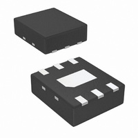
IC TEMP SENS/SWITCH 105C 6LLP
Manufacturer
National Semiconductor
Series
PowerWise®r
Datasheet
1.LM26LVEB.pdf
(20 pages)
Specifications of LM26LVCISDX-105/NOPB
Sensing Temperature
105°C Trip Point
Output Type
Active High/Push Pull, Active Low/Open Drain, Voltage
Voltage - Supply
1.6 V ~ 5.5 V
Accuracy
±2.2°C
Package / Case
6-WDFN Exposed Pad
Lead Free Status / RoHS Status
Lead free / RoHS Compliant
Other names
LM26LVCISDX-105


www.national.com
Electrical Characteristics
Unless otherwise noted, these specifications apply for +V
T
Definitions of t
Note 1: Absolute Maximum Ratings indicate limits beyond which damage to the device may occur. Operating Ratings indicate conditions for which the device is
functional, but do not guarantee specific performance limits. For guaranteed specifications and test conditions, see the Electrical Characteristics. The guaranteed
specifications apply only for the test conditions listed. Some performance characteristics may degrade when the device is not operated under the listed test
conditions.
Note 2: When the input voltage (V
Note 3: The Human Body Model (HBM) is a 100 pF capacitor charged to the specified voltage then discharged through a 1.5 kΩ resistor into each pin. The
Machine Model (MM) is a 200 pF capacitor charged to the specified voltage then discharged directly into each pin. The Charged Device Model (CDM) is a specified
circuit characterizing an ESD event that occurs when a device acquires charge through some triboelectric (frictional) or electrostatic induction processes and then
abruptly touches a grounded object or surface.
Note 4: The junction to ambient temperature resistance (θ
Note 5: Typicals are at T
Note 6: Limits are guaranteed to National's AOQL (Average Outgoing Quality Level).
Note 7: Accuracy is defined as the error between the measured and reference output voltages, tabulated in the Conversion Table at the specified conditions of
supply gain setting, voltage, and temperature (expressed in °C). Accuracy limits include line regulation within the specified conditions. Accuracy limits do not
include load regulation; they assume no DC load.
Note 8: Changes in output due to self heating can be computed by multiplying the internal dissipation by the temperature resistance.
Note 9: Source currents are flowing out of the LM26LV. Sink currents are flowing into the LM26LV.
Note 10: The 1 µA limit is based on a testing limitation and does not reflect the actual performance of the part. Expect to see a doubling of the current for every
15°C increase in temperature. For example, the 1 nA typical current at 25°C would increase to 16 nA at 85°C.
Note 11: Line regulation (DC) is calculated by subtracting the output voltage at the highest supply voltage from the output voltage at the lowest supply voltage.
The typical DC line regulation specification does not include the output voltage shift discussed in Section 4.3.
Note 12: The curves shown represent typical performance under worst-case conditions. Performance improves with larger overhead (V
and lower temperatures.
Note 13: The curves shown represent typical performance under worst-case conditions. Performance improves with larger V
temperatures.
MAX
TRIP TEST DIGITAL INPUT
TIMING
Symbol
t
V
V
V
t
; all other limits T
I
I
EN
TEMP
IH
IL
IH
IL
Logic "1" Threshold Voltage
Logic "0" Threshold Voltage
Logic "1" Input Current
Logic "0" Input Current
(Note
Time from Power On to Digital
Output Enabled. See
definition below.
Time from Power On to
Analog Temperature Valid.
See definition below.
10)
J
= T
Parameter
A
A
= T
EN
= 25°C and represent most likely parametric norm.
J
I
) at any pin exceeds power supplies (V
= 25°C.
and t
V
TEMP
20204750
V
TEMP
JA
) is specified without a heat sink in still air.
C
L
= 0 pF to 1100 pF
DD
I
= +1.6V to +5.5V. Boldface limits apply for T
< GND or V
Conditions
8
I
> V
DD
), the current at that pin should be limited to 5 mA.
(Note
Typical
0.001
1.5
1.1
1.0
5)
TEMP
V
, larger V
(Note
20204751
Limits
DD
A
0.5
2.5
2.3
2.9
− 0.5
1
= T
DD
6)
− V
DD
J
= T
and lower
TEMP
ms (max)
ms (max)
μA (max)
μA (max)
MIN
V (max)
V (min)
(Limit)
), larger V
Units
to
DD
,
Related parts for LM26LVCISDX-105/NOPB
Image
Part Number
Description
Manufacturer
Datasheet
Request
R

Part Number:
Description:
IC TEMP SENS/SWITCH 50C 6LLP
Manufacturer:
National Semiconductor
Datasheet:
Part Number:
Description:
IC TEMP SENS/SWITCH 60C 6LLP
Manufacturer:
National Semiconductor
Datasheet:
Part Number:
Description:
IC TEMP SENS/SWITCH 65C 6LLP
Manufacturer:
National Semiconductor
Datasheet:
Part Number:
Description:
IC TEMP SENS/SWITCH 70C 6LLP
Manufacturer:
National Semiconductor
Datasheet:
Part Number:
Description:
IC TEMP SENS/SWITCH 75C 6LLP
Manufacturer:
National Semiconductor
Datasheet:
Part Number:
Description:
IC TEMP SENS/SWITCH 80C 6LLP
Manufacturer:
National Semiconductor
Datasheet:
Part Number:
Description:
IC TEMP SENS/SWITCH 85C 6LLP
Manufacturer:
National Semiconductor
Datasheet:
Part Number:
Description:
IC TEMP SENS/SWITCH 90C 6LLP
Manufacturer:
National Semiconductor
Datasheet:
Part Number:
Description:
IC TEMP SENS/SWITCH 95C 6LLP
Manufacturer:
National Semiconductor
Datasheet:
Part Number:
Description:
IC TEMP SENS/SWITCH 100C 6LLP
Manufacturer:
National Semiconductor
Datasheet:

Part Number:
Description:
National Semiconductor [8-Bit D/A Converter]
Manufacturer:
National Semiconductor
Datasheet:
Part Number:
Description:
National Semiconductor [Media Coprocessor]
Manufacturer:
National Semiconductor
Datasheet:
Part Number:
Description:
Digitally Controlled Tone and Volume Circuit with Stereo Audio Power Amplifier, Microphone Preamp Stage and National 3D Sound
Manufacturer:
National Semiconductor
Datasheet:
Part Number:
Description:
Digitally Controlled Tone and Volume Circuit with Stereo Audio Power Amplifier, Microphone Preamp Stage and National 3D Sound
Manufacturer:
National Semiconductor
Datasheet:
Part Number:
Description:
AC97 Rev 2 Codec with Sample Rate Conversion and National 3D Sound
Manufacturer:
National Semiconductor