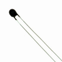
PS302J2 US Sensor, PS302J2 Datasheet - Page 23

PS302J2
Manufacturer Part Number
PS302J2
Description
THERMISTOR 3K OHM +/-0.10 C
Manufacturer
US Sensor
Series
PSr
Specifications of PS302J2
Resistance In Ohms @ 25°c
3K
B0/50
3890K
Operating Temperature
-80°C ~ 150°C
Lead Length
1.50" (38.00mm)
Mounting Type
Free Hanging
Package / Case
Bead
Lead Free Status / RoHS Status
Lead free / RoHS Compliant
Resistance Tolerance
-
B Value Tolerance
-
B25/50
-
B25/75
-
B25/85
-
B25/100
-
Power - Max
-
Other names
615-1001
Inrush Current Limiting
Power Thermistors
U.S. Sensor’s inrush current limiting power thermistors are specially formulated
and processed NTC thermistors suitable for suppressing high inrush currents in
switching power supplies and other applications where the high initial starting
currents are undesirable. Their unique design enables them to handle extremely
high current and voltage levels. In a typical power supply application, the device
is used in series with the filter capacitors. Upon application of the initial voltage,
the device, due to its relatively high resistance, limits the current flow to an
acceptable level until the capacitors are charged. Thereafter, the device decreases
in resistance substantially to a level where the voltage drop across it is negligible.
Maximum Steady State Current (I
For power thermistors, the maximum continuous
steady state current, either DC or RMS AC, which
the device is capable of passing. The maximum
steady state current for U.S. Sensor power thermis-
tors is determined assuming a maximum operating
ambient temperature of 65˚C. If a specific applica-
tion requires ambient temperature operation above
65˚C, custom designed devices are available.
Resistance At Maximum Current (RI
For power thermistors, the approximate resistance of the
device under maximum steady state current conditions.
ST1R020B
ST1R030B
ST2R018B
ST2R503B
ST2R507B
ST2R509B
ST2R510B
ST2R515B
ST5R002B
ST5R005B
ST5R007B
ST7R004B
ST10003B
ST10005B
ST10006B
ST10010B
ST20002B
ST40002B
Number
Part
R
0
Inrush Current Limiting Power Thermistors
Resistance
± 20% Ω
@ 25˚C
10.0
10.0
10.0
10.0
20.0
40.0
1.0
1.0
2.0
2.5
2.5
2.5
2.5
2.5
5.0
5.0
5.0
7.0
Max. Steady State
Current (Amps)
20
30
18
10
15
10
I
max
3
7
9
2
5
7
4
3
5
6
2
2
max
)
max
)
RI
Current Ω
@ Max.
max
0.015
0.015
0.030
0.150
0.050
0.040
0.040
0.030
0.400
0.100
0.070
0.200
0.200
0.200
0.150
0.100
0.600
0.600
Resis.
22
1832 West Collins Avenue, Orange, CA 92867 • Tel. (714) 639-1000 • Fax (714) 639-1220 • www.ussensor.com
(Max. Over
0.310" NOM
Dim. “D”
Coating)
0.900”
1.250”
1.250”
0.900"
0.600"
0.600"
0.600"
0.900"
0.900"
0.600"
0.600"
0.600"
0.600"
0.450"
0.600"
0.600"
0.500"
0.625"
(Max. Over
Dim. “T”
Coating)
0.300”
0.250”
0.300”
0.250"
0.250"
0.250"
0.300"
0.300"
0.250"
0.250"
0.250"
0.300"
0.300"
0.350"
0.350"
0.300"
0.250"
0350"
TINNED SOLDERABLE WIRE
SEE CHART FOR LEAD DIAMETER
1.0" MIN
Lead Dia.
0.040”
0.040”
0.040”
(Nom.)
0.040"
0.032"
0.032"
0.032"
0.040"
0.040"
0.032"
0.032"
0.032"
0.040"
0.032"
0.040"
0.040"
0.032"
0.032"
The circuit diagram above
demonstrates a typical method to
limit inrush current at turn on in
a power supply. Two or more
inrush current limiting devices
may be used in series or in sepa-
rate legs of the supply circuit.
The devices may not be used in
parallel since one will tend to
pass nearly all the current avail-
able. U.S. Sensor’s inrush current
limiters may be used in either the
AC or DC portions of the circuit.
PROTECTIVE COATING
D
T


