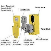
LM3 BANNER ENGINEERING, LM3 Datasheet - Page 13

LM3
Manufacturer Part Number
LM3
Description
Photoelectric Sensor
Manufacturer
BANNER ENGINEERING
Datasheet
1.LM1.pdf
(32 pages)
Specifications of LM3
Timing Function
On-Delay And Off-Delay
Time Range
None To Output Follows Input
Application
Interconnecting the power block and scanner block
Brand/series
Multi-Beam®
Function
Module, Logic
Includes
Blade & socket connector
Logic Type
ON⁄OFF, Light or Dark Operate
Sensing Mode
Adjustable Field
Technology
Photoelectric
Accessory Type
Logic Module
Lead Free Status / Rohs Status
RoHS Exempt Product
For Use With
Multi-Beam Sensors
Available stocks
Company
Part Number
Manufacturer
Quantity
Price
Part Number:
LM30-00J051203E
Manufacturer:
MONRSUN
Quantity:
20 000
Part Number:
LM3000ASQ/NOPB
Manufacturer:
NS/国半
Quantity:
20 000
Company:
Part Number:
LM3000SQ/NOPB
Manufacturer:
National Semiconductor
Quantity:
1 820
Company:
Part Number:
LM300Q5
Manufacturer:
SAMSUNG
Quantity:
1 000
Company:
Part Number:
LM300W01-A1
Manufacturer:
SAMSUNG
Quantity:
1 000
Company:
Part Number:
LM300W01-STA1
Manufacturer:
SAMSUNG
Quantity:
1 000
Company:
Part Number:
LM300W01-STA4 L
Manufacturer:
SAMSUNG
Quantity:
1 000
Scanner block model SBFV1 supplies visible red light to the emitter half of a glass fiber optic photoelectric system. Visible light sensors have less optical energy
as compared to infrared systems. There are, however, some sensing situations which require visible light wavelengths in order to realize adequate optical contrast.
Opposed fibers using visible red light are used to reliably sense translucent materials (e.g. plastic bottles) which appear transparent to infrared opposed sensors. Fiber
assembly model BT13S used with a the model L9 or L16F lens makes an excellent visible light sensing system for retroreflective code reading as well as many short-
range retroreflective applications (e.g. retro scanning across a narrow conveyor). When combined with a bifurcated fiber, model SBFV1 may be used for color
registration sensing for applications where there is a large difference between the two colors (e.g. black-on-white). For combinations of red-on-white, however,
the visible-green light source of model SBFVG1 (below) is needed. Visible light emitters are also helpful for visual system alignment and maintenance.
MULTI-BEAM
VISIBLE GREEN LIGHT SOURCE
VISIBLE RED LIGHT SOURCE
FIBER OPTIC Mode
(glass fiber optics)
OPPOSED MODE
RETROREFLECTIVE MODE
DIFFUSE MODE
(REGISTRATION CONTROL)
FIBER OPTIC Mode
(glass fiber optics)
for COLOR SENSING
Sensing Mode
OBJECT
OBJECT
RETRO TARGET
OBJECT
SBFV1
Range: see excess gain
curves
Response: 1ms on/off
Repeatability: 0.3ms
Beam: visible red, 650nm
Fiber optic information:
IT13S: individual assembly
.06in (1,5mm) dia. bundle
IT23S: individual assembly
.12 in. (3mm) dia. bundle
BT13S: bifurcated assem-
bly, .06 in. (1,5mm) dia.
bundle
BT23S: bifurcated assem-
bly, .12 in. (3mm) dia.
bundle
L9: .5in. (12mm) dia. lens
L16F: 1.0 in. (25mm) dia.
lens
For information on the
complete line of glass fiber
optics, see Banner product
catalog.
Convergent beam sensors like model SBCVG1 are often used for color registration sensing. However, there are
some registration applications where the use of bifurcated fiber optics is beneficial. Fiber optics are able to fit
into tight locations which are too small for a convergent sensor. Fibers also allow a choice of image size. It is
important to create an image size which is smaller than the registration mark in order to maximize optical contrast
and to ease sensor response requirements. Fibers allow a match of the light image to the geometry of the
registration mark. Scanner block model SBFVG1 will sense most bold color differences, including red-on-white.
Use only power blocks which switch dc (e.g. PBT, PBP, PBO, PBAT, etc.) for fast response.
SBFVG1
Range:
Response: 1 ms on/off
Repeatability: 0.3ms
Beam: visible green,
560nm
3- & 4-wire Scanner Blocks
Models
see excess gain curve
E
X
C
E
S
S
G
A
I
N
E
X
C
E
S
S
G
A
I
N
E
X
C
E
S
S
G
A
I
N
E
X
C
E
S
S
G
A
I
N
I
I
I
I
1000
1000
1000
1000
100
100
100
100
10
10
10
10
.01 IN
..1 IN
..1 FT
.01 IN
1
1
1
1
Excess Gain
with IT23S
fibers
Retroreflective mode,
with BRT-3 reflector
BT13S fibers
Diffuse mode
Diffuse mode
with L9 lens,
BT13S fiber
with IT13S
fibers
1 IN
1 FT
.1 IN
.1 IN
DISTANCE
DISTANCE
DISTANCE
DISTANCE
(Range based on
90% reflectance
white test card)
(Range based on
90% reflectance
white test card)
BT23S fibers
Opposed mode
BT23S
fiber
SBFVG1
SBFV1
SBFV1
10 IN
10 FT
SBFV1
1 IN
1 IN
with L16F lens,
BT13S fiber
with IT23S
fibers, L9
lenses
100 IN
100 FT
10 IN
10 IN
I
N
C
H
E
S
I
N
C
H
E
S
I
N
C
H
E
S
I
N
C
H
E
S
.075
.025
.025
.075
.075
.025
.025
.075
1.0
1.5
1.5
DISTANCE TO 90% WHITE TEST CARD--INCHES
DISTANCE TO 90% WHITE TEST CARD--INCHES
1.0
.05
.05
.05
.05
Beam Pattern
.5
0
0
.5
0
0
2
4
6
6
2
4
0
0
0
0
SBFV1
SBFVG1
SBFV1 opposed mode
SBFV1 retroreflective mode
with
L9 lenses
IT13S fibers
OPPOSED DISTANCE--INCHES
DISTANCE TO REFLECTOR--FEET
BT13S fibers
.3
.1
3
4
BT23S fiber
diffuse mode
.6
.2
6
8
with
L16F lenses
with BRT-3 reflector
IT23S fibers
9
12
.9
.3
BT13S fibers
BT23S fibers
12
16
1.2
.4
15
20
1.5
.5
13


