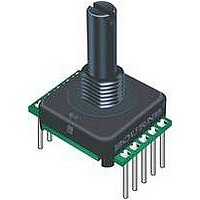
Until now, the choice of an absolute
encoder meant an expensive, and larger-
sized product. Through the use of
combinatorial mathematics, the absolute
code pattern of the Bourns Absolute
Contacting Encoder ACE
single track for a very economical, energy-
effi cient and compact product. Bourns’
ACE
that will also retain its last position in the
event of a power failure.
An intelligent alternative to incremental
encoders and potentiometers, the Bourns
ACE
automotive, medical and consumer prod-
uct applications.
Output ............................................................................................................................................................................ 8-bit code with 128 absolute states
Closed Circuit Resistance .......................................................................................................................................................................... 5 ohms maximum
Open Circuit Resistance .......................................................................................................................................................................100 K ohms minimum
Contact Rating ................................................................................................................................................. 10 milliamp @ 10 VDC or 0.1 watt maximum
Insulation Resistance (500 VDC) ................................................................................................................................................... 1,000 megohms minimum
Dielectric Withstanding Voltage (MIL-STD-202 Method 301)
Electrical Travel..................................................................................................................................................................................................... Continuous
Contact Bounce (60 RPM) ...........................................................................................................................................................2.7 milliseconds maximum*
RPM (Operating) ............................................................................................................................................................................................... 120 maximum
Operating Temperature Range ...................................................................................................................................... -40 ºC to +85 ºC (-40 °F to +185 °F)
Storage Temperature Range ......................................................................................................................................... -40 ºC to +85 ºC (-40 °F to +185 °F)
Humidity ............................................................................................................................................................... MIL-STD-202, Method 103B, Condition B
Vibration .......................................................................................................................................................................................................................... 15 G
Shock .............................................................................................................................................................................................................................. 50 G
Rotational Life ...................................................................................................................................................................50,000 shaft revolutions minimum
IP Rating ..........................................................................................................................................................................................................................IP 40
Mechanical Angle ........................................................................................................................................................................................360 ° Continuous
Running Torque ..............................................................................................................................................................0.5 to 1.5 N-cm (0.75 to 2.50 oz-in.)
Mounting Torque ....................................................................................................................................................................... 79 N-cm (7 lb.-in.) maximum
Shaft Side Load (Static) ................................................................................................................................................................... 4.5 kg (10 lbs.) minimum
Weight ................................................................................................................................................................................ Approximately 14 gms. (0.50 oz.)
Terminals ................................................................................................................................................................................ Printed circuit board terminals
Soldering Condition
Marking ..........................................................................................................................Manufacturer’s name and trademark, part number, and date code.
Hardware ............................................... One lockwasher and one mounting nut are shipped with each encoder, except where noted in the part number.
Packaging .............................................................................................................................................................................................................45 pcs./tray
*High probability of missing quadrature codes with maximum bounce.
*RoHS Directive 2002/95/EC Jan 27, 2003 including Annex.
Customers should verify actual device performance in their specifi c applications
Specifi cations are subject to change without notice.
Electrical Characteristics
Environmental Characteristics
Mechanical Characteristics
General Information
Sea Level ............................................................................................................................................................................................ 1,000 VAC minimum
Contact Bounce..........................................................................................................................................................................0.1 millisecond maximum
Contact Bounce..........................................................................................................................................................................0.1 millisecond maximum
Manual Soldering .................................................................................................................. 96.5Sn/3.0Ag/0.5Cu solid wire or no-clean rosin cored wire
Wave Soldering...........................................................................................................................................96.5Sn/3.0Ag/0.5Cu solder with no-clean fl ux
Wash processes ....................................................................................................................................................................................Not recommended
™
™
provides an absolute digital output
is ideally suited for many industrial,
™
is placed on a
Features
■
■
■
■
■
■
EAW - Absolute Contacting Encoder (ACE™)
“common” is either
on a decoded
“select” pin
(active low)
or at GND.
Recommended Control Diagram for ACE-128
*RoHS compliant
Absolute encoder / absolute code output
Digital output
Sturdy construction
Bushing mount
Available with PC board mounting bracket (optional)
C
1
2
3
4
P
P
1
P
2
P
3
P
C
8
7
6
5
4
P
5
P
6
370 °C (700 °F) max. for 3 seconds
260 °C (500 °F) max. for 5 seconds
P
7
P
8
RESNET
4609X-
101-472
ACETAB:
256 byte
code
conversion
table (ROM)


