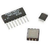
HMC6352 Honeywell Microelectronics & Precision Sensors, HMC6352 Datasheet

HMC6352
Specifications of HMC6352
Available stocks
Related parts for HMC6352
HMC6352 Summary of contents
Page 1
... Digital Compass Solution HMC6352 The Honeywell HMC6352 is a fully integrated compass module that combines 2-axis magneto-resistive sensors with the required analog and digital support circuits, and algorithms for heading computation. By combining the sensor elements, processing electronics, and firmware 6.5mm by 6.5mm by 1.5mm LCC package, Honeywell offers a complete, ready to use electronic compass ...
Page 2
... HMC6352 HMC6352 SPECIFICATIONS Characteristics Supply Voltage Supply Current Sleep Mode (Vsupply = 3.0V) Steady State (Vsupply = 3.0V) Steady State (Vsupply = 5.0V) (2) Field Range Heading Accuracy Heading Resolution Heading Repeatability Disturbing Field Sensitivity starts to degrade. Enable set/reset function to restore sensitivity. Max. Exposed No permanent damage and set/reset function ...
Page 3
... The default (factory) HMC6352 7-bit slave address is 42(hex) for write operations, or 43(hex) for read operations. The HMC6352 Serial Clock (SCL) and Serial Data (SDA) lines do not have internal pull-up resistors, and require resistive pull-ups (Rp) between the master device (usually a host microprocessor) and the HMC6352. Pull-up resistance values of about 10k ohms are recommended with a nominal 3 ...
Page 4
... All bus transactions are terminated with the master issuing a stop sequence. The following timing diagram shows an example of a master commanding a HMC6352 (slave) into sleep mode by sending the “S” command. The bottom two traces show which device is pulling the SDA line low. ...
Page 5
... The “S” command returns the processor to sleep mode. The three operational modes are defined by two bits in the internal HMC6352 Operation Mode register. If the master device sends the “L” command, the current operational mode control byte in the RAM register is loaded into the internal EEPROM register and becomes the default operational mode on the next power-up ...
Page 6
... Exposure of the HMC6352 to magnetic fields above 20 gauss (disturbing field threshold) leads to possible measurement inaccuracy or “stuck” sensor readings until the set/reset function is performed. With the periodic Set/Reset bit set, the set/reset function occurs every few minutes ...
Page 7
... The calibration routine collects these readings to correct for hard-iron distortions of the earth’s magnetic field. These hard- iron effects are due to magnetized materials nearby the HMC6352 part that in a fixed position with respect to the end user platform. An example would be the magnetized chassis or engine block of a vehicle in which the compass is mounted onto ...
Page 8
... All commands are accepted in the standby mode. Honeywell strongly recommends using this mode during the initial setup stage. Setting up of the HMC6352 operation mode and its slave address are typical set up examples. Although execution of all commands in the Query and Continuous Modes is acceptable, the completion outcome is not guaranteed. ...
Page 9
... M_SDA S_SDA S_SDA S_SDA 42(hex) Write to This I2C Address Example 4: This example shows how to write to a RAM register in the HMC6352 by sending the “G” command, the register address 7F(hex), and the data byte 55(hex) to the HMC6352 slave. SDA SDA SDA SCL ...
Page 10
... PCB Pad Definition (Dimensions in Millimeters) The HMC6352 is a fine pitch LCC package with a 0.80mm pin pitch (spacing), with the pin pads defined as 0.70mm by 0.33mm in size. PCB pads are recommended to be oversized by 0.025mm from each pad for a short dimension oversize of 0.05mm. The interior PCB pad is recommended to be 0.05mm oversized per pin with an exterior oversize of 0.20mm for proper package centering and to permit test probing ...
Page 11
... A 1.37 SOLDERING GUIDELINES Most LCC packages have no special requirements beyond normal procedures for attaching SMT components to printed circuit boards. The exception to this process is the Honeywell HMC6352 that has a FR4 substrate package with epoxy top encapsulation. www.honeywell.com 24 24 TOP VIEW TOP VIEW ...
Page 12
... The 0.01µF supply decoupling capacitor in this reference can be omitted if another supply filter capacitor is already included in the overall circuit design. If the supply traces extend beyond a couple inches to the HMC6352 advisable to add a local supply decoupling capacitor near the HMC6352 to retain optimum circuit stability. ...
Page 13
... The HMC6352 design has provisions for the feedback loop of each amplifier stage to be accessible via the CA1, CA2, CB1, and CB2 pin contacts. Across the contacts and internal to the HMC6352 is the amplifier section plus a 1200k-ohm feedback resistance to set the voltage gain. By placing small value ceramic capacitors across CA1 to CA2 (or CB1 to CB2), the designer can set the – ...


