GFL631T-3 INSTRUMENT TRANSFORMER, GFL631T-3 Datasheet
GFL631T-3
Specifications of GFL631T-3


Related parts for GFL631T-3

GFL631T-3 Summary of contents
Page 1
Electronic Products Electronic Products Ground F ault S Ground F ault S yst ems yst ems ...
Page 2
USA, Canada, Asia, Latin America Tel: +1-800-547-8629 Fax: +1-905-201-2455 e-mail: sales.multilin@ge.com Please refer to our website www.GEMultilin.com for more detailed contact information www.GEMultilin.com Europe, Middle East , Africa Tel: +34-94-485-88-00 Fax: +34-94-485-88-45 e-mail: gemultilin.euro@ge.com Electronic Products ...
Page 3
GROUND FAULT SYSTEMS GROUND FAULT SYSTEMS Model GFA Relays Model GFA Sensors Model GFM Relays Model GFM Sensors Model BGFL Relay Model GFL Sensors www.GEMultilin.com Ground Fault Current Detection System Relay . . . . . . . . . ...
Page 4
THREE PHASE VOLTAGE M THREE PHASE VOLTAGE M Model SPVRA Model SPVRB Model LPVRB Model APVR VOLTAGE TRANSDUCERS VOLTAGE TRANSDUCERS Model LLV & Model PNV www.GEMultilin.com ONITO RING ONITO RING Phase Voltage Relay . . . . . . . ...
Page 5
CURRENT TRANSDUCERS CURRENT TRANSDUCERS Model ACV Model 10ACV Model PCL Model PCL Model PCM OPEN CIRCUIT PROTECTO OPEN CIRCUIT PROTECTO Model OCP www.GEMultilin.com AC Current Transducers . . . . . . . . . . . . . . ...
Page 6
CAPACITO R TRIP DEVICES CAPACITO R TRIP DEVICES Model CTD -1 & 2 Model CTD - 3 Model CTD - 4 Model CTD - 5 Model CTDA-6 Model CTDB - 6 www.GEMultilin.com Capacitor Trip Device . . . . . ...
Page 7
Ground Fault Current Detection Systems Model GFA (Relay Amp Trip Currents OPERATING RANGE: Trip currents of 10,15, 20 & 75 Amperes. Time delay from 0. seconds. INPUT POWER: Self powered. FREQUENC Y: 50/60 Hz. AMBIENT ...
Page 8
Ground Fault Current Detection Systems Model GFA (Sensor Amp Trip Currents OPERATING RANGE: Trip currents of 10,15,20 & 75 Amperes. Trip current tolerance percent . FREQUENC Y: 50/60 Hz. INSULATION LEVEL: 600 Volt , ...
Page 9
Ground Fault Current Detection Systems Model GFM (Relay) 1 Amp Trip Currents ADJUSTABLE OPERATING RANGE: Trip currents from 1 Amperes. Time delay from instantaneous to 36 cycles. INPUT POWER: Self powered. FREQUENC Y: 50/60 Hz. AMBIENT ...
Page 10
Ground Fault Model GFM (Sensor ) 1 Amp Trip Currents OPERATING RANGE: INSULATION LEVEL: 600 Volt , 10 kV BIL full wave. Trip currents from 1.5 -7 Amperes. Terminals are brass studs No. 8-32. ...
Page 11
Pick-Up and Time Delay Characteristics Pick-Up and Time Delay Characteristics ITI GFM sensors are assigned a current range to indicate a pick-up current level. The GFM relay has a range select from “A” to “D”. “A” is the lowest current ...
Page 12
A Simulated fault current can be applied by the above test circuit . An appropriate value of R1 should be selected to apply a minimum of 1.5 times maximum trip rating of the sensor. 1. Assure that the GFM relay ...
Page 13
Ground Fault Current Detection Systems Model BGFL (Relay) Trip Currents 360 , These Class 1 Model BGFL Ground Fault Relays and Sensors are designed to ...
Page 14
Ground Fault Current Detection Systems Model BGFL ( USA, Canada, Asia, Latin America Tel: +1-800-547-8629 Fax: +1-905-201-2455 e-mail: sales.multilin@ge.com 8 Please refer to our website www.GEMultilin.com for more detailed contact information ...
Page 15
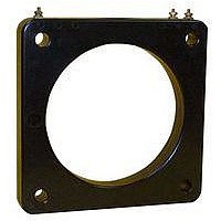
... GFL250T-3 2.50 * 4.56 * 4.71 GFL325T-3 3.25 4.70 5.73 4.70 5.73 GFL425T-3 4.25 4.86 5.92 ** 6.17 GFL631T-3 6.31 6.75 8.50 6.75 8.50 GFL825T-3 8.25 8.50 10.48 8.50 10.48 1.53 TRIP CURRENT 100-1200 AMPS GFL325T-2 3.25 4.70 5.73 4.70 5.73 GFL425T-2 4.25 4.86 5 ...
Page 16
Ground Fault Current Detection Systems Model GFL ( Trip Currents 360 , Rectangular Sensors Rectangular sensors are available ...
Page 17
Cardinal points are shown for clarity only. The actual time delay adjustment is continuously variable between instantaneous and 1 second. The time delay tolerance is + 15% of setting. To determine if the neutral is grounded in only one place ...
Page 18
TYPICAL WIRING DIAGRAM FOR "STANDARD" TYPICAL WIRING DIAGRAM FOR “ STANDARD” AND "ZONE INTERLOCKING" CIRCUITRY AND “ZONE INTERLOCKING” CIRCUITRY (BGFLXX7-XXXX AND BGFLXX9-XXXX) (BGFLXX7-XXXX AND BGFLXX9-XXXX) Typical Wiring Diagram Zone Selective Interlocking BGFLXX7 RELAY CONTACT 6 COMMON 7 OUTPUT (Note:# 2) ...
Page 19
Three Phase Voltage Monitor Model SPVRA STANDARD FEATURES • Phase Unbalance • Adjustable Trip Delay seconds after failure occurs. • Output Relay: normally de-energized: Form C contacts for easy circuit conf iguration. • Electro - ...
Page 20
A correctly installed SPVRA Voltage Sensing Relay will protect a power system against damage due to single phase and phase loss, phase reversal, phase unbalance , and under and over voltage. When operating under normal power conditions, the bi-colored LED ...
Page 21
Three Phase Voltage Monitor Model SPVRB • Phase Unbalance • Adjustable Trip Delay seconds after failure occurs. • Output Relay: normally de-energized: Form C contacts for easy circuit conf iguration. • Electro - Mechanical Indicator: ...
Page 22
A correctly installed SPVRB Voltage Sensing Relay will protect a power system against damage due to single phase and phase loss, phase reversal , phase unbalance . When operating under normal power conditions, the bi-colored LED “ Relay Status ” ...
Page 23
... The Model LPVRB is designed to protect 3-phase loads from damaging power conditions.Its wide operating range combined with UL and CE compliance • insures worldwide acceptance. For Complete information on warranty, liability terms, returns, and cancellations, please refer to the Instrument Transformers,Inc Standard Conditions of Sale. www.GEMultilin.com Specif ications: • ...
Page 24
Pick-UP Adjust Unbalance Adjust A unique microcontroller-based voltage and phase sensing circuit constantly monitors the three phase voltages to detect harmful power line conditions. When a harmful condition is detected, the LPVRB’s output relay is deactivated after a specif ied ...
Page 25
Phase Loss Phase Sequence Detection System Model APVR SPECIFICATIONS • Failsafe: Trip free contacts will not operate if a fault is present . • Automatic reset . (Conf igurable to manual reset , See applications notes.) • Fixed undervoltage trip ...
Page 26
If the power conditions are normal, 3 seconds after power is supplied to the APVR the contacts will transfer, permitting operation. In normal applications, this power will already be applied to the AP VR and there is no time delay ...
Page 27
Voltage Transducers Model LLV & PNV APPLICATION: 3 Phase voltage measurement . NOMINAL INPUT VOLTAGES: 120V, 240V, 277V, 480V FREQUENC Y: 50/60 Hz. ACCURACY: + 0.5% Full scale. AMBIENT TEMPERATURE RANGE: o Effect on accuracy ...
Page 28
AC Current Transducer Model ACV 0 200 A to produce 0 - OPERATING RANGE: Primary 200 Amps ac. Secondary Volts dc. FREQUENC Y: 50/60 Hz. INSULATION LEVEL: 600 Volts BIL full wave. RESPONSE ...
Page 29
AC Current Transducer Model 10ACV 0 200 Amps to produce 0 - OPERATING RANGE: Primary 200 Amps ac. Secondary Volts dc. FREQUENC Y: 50/60 Hz. INSULATION LEVEL: 600 Volts BIL full wave. RESPONSE ...
Page 30
AC Current Transducer Model PCL 0 75 Amps ac to produce 4 - OPERATING RANGE: Input 5 thru 75 Amps ac. Output: 4-20 mA dc. FREQUENC Y: 50/60 Hz. AMBIENT TEMPERATURE RANGE: o Effect on accuracy + 0.02 ...
Page 31
AC Current Transducer Model PCL 0 600 Amps ac to produce 4 - OPERATING RANGE: Input 0 to 100 thru 600 Amps ac. Output: 4-20 mA dc. FREQUENC Y: 50/60 Hz. AMBIENT TEMPERATURE RANGE: o Effect on accuracy + 0.02%/ ...
Page 32
AC Current Transducer Model PCM 0- OPERATING RANGE: Input 0-5 thru 300 Amps ac. Output: 4-20 mA dc. ...
Page 33
Application #1 APPLICATION #1 APPLICATION #2 Application #2 Example EXAMPLE APPLICATION #3 Application #3 Calculating Rated Input Rated Input Where: NOTE: Output current of each PCM is limited to 30mA max. From this the required by using capacity of the ...
Page 34
Open Circuit Protectors Model OCP APPLICATION: Open circuit protection for relay classes through C800 and all classes through C800 and metering classes. FREQUENCY: 50-400 Hz. 1 ELEMENT OPEN CIRCUIT PROTECTOR RECOMMENDED CLAMPING PEAK MODEL CT RELAYING VOLTAGE LIMIT NUMBER CLASS ...
Page 35
TYPICAL 1 ELEMENT CONNECTION DIAGRAM 1-OCP-XXX A Current Transformer secondary should never be open circuited white the Current Transformer primary circuit is energized. If this situation should occur there is a possibility of developing extremely high voltages which could be ...
Page 36
Capacitor Trip Device Model CTD 1 & CTD - APPLICATION: Provides a source of energy for circuit breaker and switch trip coil operation during a loss of AC control voltage. NORMAL INPUT: 120 Volts ac, 125 Volts dc. FREQUENCY: DC ...
Page 37
Capacitor Trip Device Model CTD 3 - APPLICATION: Provides a source of energy for circuit breaker and switch trip coil operation during a loss of AC control voltage. NORMAL INPUT: 240 Volts ac AMBIENT TEMPERATURE RANGE -30 C ...
Page 38
Capacitor Trip Device Model CTD 4 - APPLICATION: NORMAL INPUT: Provides a source of 120 VAc or 240 VAC energy for circuit breaker and switch trip coil FREQUENCY: operation during a loss control voltage. • These ...
Page 39
Capacitor Trip Device Model CTD 5 - APPLICATION: Provides a source of energy for circuit breaker and switch trip coil operation during a loss of AC control voltage. NORMAL INPUT: 120/240 Volts ac. FREQUENCY 400Hz. • These devices ...
Page 40
Capacitor Trip Device Model CTDA 6 - APPLICATION: Provides a source of energy for circuit breaker in the event of a power loss. Tripping power is available immediately upon energization before capacitors charged. NORMAL INPUT: 120/240 Volts ac. • The ...
Page 41
Capacitor Trip Device With Battery Back-Up Model CTDB 6 - APPLICATION: Provides a source of energy for circuit breaker and switch trip coil operation during a loss of AC control voltage. Tripping power is available immediately upon energization before capacitors ...
Page 42
Operation: Nominal ac volts is applied across terminals #8 and #10. This voltage is full wave bridge rectif ied and applied across the trip capacitors producing a steady state output trip voltage. The charge stored in these capacitor is available ...
Page 43
Electronic Products ...
Page 44
USA, Canada, Asia, Latin America Tel: +1-800-547-8629 Fax: +1-905-201-2455 e-mail: sales.multilin@ge.com Please refer to our website www.GEMultilin.com for more detailed contact information Electronic Products Europe, Middle East , Africa Tel: +34-94-485-88-00 Fax: +34-94-485-88-45 e-mail: gemultilin.euro@ge.com CCS-ELEC Rev.5 1/07 ...