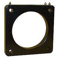
GFL631T-3 INSTRUMENT TRANSFORMER, GFL631T-3 Datasheet - Page 17

GFL631T-3
Manufacturer Part Number
GFL631T-3
Description
GROUND FAULT CURENT
Manufacturer
INSTRUMENT TRANSFORMER
Datasheet
1.GFL631T-3.pdf
(44 pages)
Specifications of GFL631T-3
Accuracy
15%
Current Measuring Range Ac
30A To 360A
www.GEMultilin.com
To determine if the neutral is grounded in only one place at the service entrance ( in accordance with The National
Electrical Code):
1. Disconnect power.
2. Remove ground bond link.
3. With a “megger”, measure the resistance of each phase and neutral to ground. The resistance should be 1 megohm in
4. Reconnect bond link, reconnect power and check power LED for illumination.
To test the entire system including the disconnect device:
1. Check for control power, the LED should be illuminated.
2. Press the “Push To Test ” switch on the relay. The trip indicator will go to the tripped position and disconnect device will
3. Reset the relay and the disconnect device. System is now back to normal.
To test the ground Fault Relay and Sensor only (The sensor will trip the relay in this tes t ).
1. Check for control power, the LED should be illuminated.
2. Press and HOLD the “Shunt Trip Bypass” switch on the relay.
3. Press the “Push To Test” switch. The Ground Fault Relay will trip.
4. Reset the relay, then release the “Shunt Trip Bypass” switch. System is now back to norm al.
accordance with NE C requirements. Reading as low as 100 ohms will pass a minimal current so as not to affect BGFL
calibration on the 100 - 1200A relay. The 5-60A and 30-360A relay calibration will be affected if set at the lowest
setting.
open.
Cardinal points are shown for clarity only.
The actual time delay adjustment is continuously variable between instantaneous and 1 second. The time delay
tolerance is + 15% of setting.
THE ABOVE TEST PROCEDURES SHOULD BE PERFORMED BY QUALIFIED PERSONNEL ONLY.
Typical Response Curves
Test Procedure
11


