M12PDQ8 BANNER ENGINEERING, M12PDQ8 Datasheet - Page 3
M12PDQ8
Manufacturer Part Number
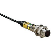
M12PDQ8
Description
Photoelectric Sensor
Manufacturer
BANNER ENGINEERING
Datasheet
1.SMBQS12PD.pdf
(8 pages)
Specifications of M12PDQ8
Output Current
100mA
Sensor Output
PNP
Supply Voltage Range Dc
10V To 30V
Sensor Housing
Barrel
Sensor Input
Optical
Body Material
Nickel-Plated Brass
Supply Voltage Max
30VDC
Sensing Range Max
400mm
Contact Current Max
20mA
Sensing Mode
Diffuse


Background Reflectivity and Placement
Avoid mirror-like backgrounds that produce specular reflections. False sensor response will
occur if a background surface reflects the sensor’s light more strongly to the near detector,
or “sensing” detector (R1) than to the far detector, or “cutoff” detector (R2). The result is a
false ON condition (Figure 4). Use of a diffusely-reflective (matte) background will cure this
problem. Other possible solutions are to angle the sensor or angle the background (in any
plane) so the background does not reflect light back to the sensor (see Figure 5). Position the
background as far beyond the cutoff distance as possible.
An object beyond the cutoff distance, either stationary (and when positioned as shown in
Figure 6), or if it moves past the face of the sensor in a direction perpendicular to the sensing
axis, can cause unwanted triggering of the sensor if it reflects more light to the near detector
than to the far detector. The problem is easily remedied by rotating the sensor 90° (Figure 7).
The object then reflects the R1 and R2 fields equally, resulting in no false triggering. A better
solution, if possible, may be to reposition the object or the sensor.
Color Sensitivity
The effects of object reflectivity on cutoff distance, though small, may be important for some
applications. It is expected that at any given cutoff setting, the actual cutoff distance for lower
reflectance targets will be slightly shorter than for higher reflectance targets. This behavior is
known as color sensitivity.
The excess gain curves on page 5 were generated using a white test card of 90% reflectance.
Objects with reflectivity of less than 90% reflect less light back to the sensor, and thus
require proportionately more excess gain in order to be sensed with the same reliability as
more reflective objects. When sensing an object of very low reflectivity, it may be especially
important to sense it at or near the distance of maximum excess gain.
Figure 6. Object beyond cutoff – problem
M12..FF..
E
R2 = Far Detector
R1 = Near Detector
A reflective background object in this position or
moving across the sensor face in this axis and
direction may cause false sensor response.
= Emitter
Banner Engineering Corp. • Minneapolis, MN U.S.A
www.bannerengineering.com • Tel: 763.544.3164
R2
R1
E
Sensing
Fixed
Field
Distance
Cutoff
Moving Object
Background
Reflective
or
M12..FF..
Figure 7. Object beyond cutoff – solution
E
R2 = Far Detector
R1 = Near Detector
A reflective background object in this position or
moving across the sensor face in this axis will be
ignored.
= Emitter
E, R2, R1
Sensing
Fixed
Field
Distance
Cutoff
M12 Series Metal Barrel Sensors
Moving Object
Background
Reflective
or
Figure 4. Reflective background – problem
Figure 5. Reflective background – solution
M12..FF..
E
R2 = Far Detector
R1 = Near Detector
M12..FF..
= Emitter
E
R2 = Far Detector
R1 = Near Detector
R2
R1
E
= Emitter
R2
R1
E
Core of
Emitted
Beam
Fixed Sensing
Core of
Emitted
Beam
Sensing
Field
Fixed
Field
Strong
Direct
Reflection
to R1
P/N 129721 rev. D
Cutoff
Distance
Cutoff
Distance
Strong
Direct
Reflection
Away
From Sensor
Reflective
Background
Reflective
Background
3
Related parts for M12PDQ8
Image
Part Number
Description
Manufacturer
Datasheet
Request
R

Part Number:
Description:
Photoelectric Sensor
Manufacturer:
BANNER ENGINEERING
Datasheet:

Part Number:
Description:
Photoelectric Sensor
Manufacturer:
BANNER ENGINEERING
Datasheet:

Part Number:
Description:
LEDIR70XD4-XM-81039 MAX INTENS STROBE ONLY NO BANNER MARKS
Manufacturer:
BANNER ENGINEERING
Part Number:
Description:
M18SP6DL-72225 LABELED MOELLER NO BANNER MARKINGS BULK PACK
Manufacturer:
BANNER ENGINEERING
Part Number:
Description:
M18SP6DLQ-72226 LABLED MOELLER NO BANNER MARKINGS BULK PACK
Manufacturer:
BANNER ENGINEERING
Part Number:
Description:
M18SP6L-72223 LABELED MOELLER NO BANNER MARKINGS BULK PACK
Manufacturer:
BANNER ENGINEERING
Part Number:
Description:
M18SP6LQ-72224 LABELED MOELLER NO BANNER MARKINGS BULK PACK
Manufacturer:
BANNER ENGINEERING
Part Number:
Description:
Photoelectric Sensor
Manufacturer:
BANNER ENGINEERING
Datasheet:

Part Number:
Description:
Programmable Indicator Light
Manufacturer:
BANNER ENGINEERING
Datasheet:
Part Number:
Description:
INDICATOR LED PANEL 50MM GRN/RED/YEL 30V
Manufacturer:
BANNER ENGINEERING
Datasheet:
Part Number:
Description:
Programmable Indicator Light
Manufacturer:
BANNER ENGINEERING
Datasheet: