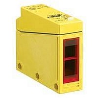
Q85VR3DL-T9 BANNER ENGINEERING, Q85VR3DL-T9 Datasheet - Page 2
Q85VR3DL-T9
Manufacturer Part Number
Q85VR3DL-T9
Description
Photoelectric Sensor
Manufacturer
BANNER ENGINEERING
Datasheet
1.Q85VR3DL-T9.pdf
(2 pages)
Specifications of Q85VR3DL-T9
Output Current
3A
Sensing Range Max
1m
Sensor Input
Laser


Hookup and timing logic selection
Hookup to the ac line and the external load is made at the five terminals
inside the wiring chamber (see drawing below). There is no polarity for
power supply hookup. Output is an SPDT electromechanical relay.
Dimensions, Q85 diffuse mode sensors
The output timing logic function (on sensor models with T9 model
number suffix) is selected at the timing logic programming switches,
according to the table (right). The output timing logic delays are set at
WARRANTY: Banner Engineering Corporation warrants its products to be free from defects for one year. Banner Engineering Corporation will repair or replace, free
of charge, any product of its manufacture found to be defective at the time it is returned to the factory during the warranty period. This warranty does not cover damage
or liability for the improper application of Banner products. This warranty is in lieu of any other warranty either expressed or implied.
Banner Engineering Corp. 9714 10th Avenue No., Minneapolis, MN 55441 Telephone: (612) 544-3164 FAX (applications): (612) 544-3573
WARNING
applications. A sensor failure or malfunction can result in either an energized or a de-energized sensor output condition.
Never use this product as a sensing device for personnel protection. Its use as a safety device may create an unsafe condition which could lead to seri-
ous injury or death. Only MACHINE-GUARD and PERIMETER-GUARD Systems, and other systems so designated, are designed to meet OSHA and
ANSI machine safety standards for point-of-operation guarding devices. No other Banner sensors or controls are designed to meet these standards, and
they must NOT be used as sensing devices for personnel protection.
This photoelectric presence sensor does NOT include the self-checking redundant circuitry necessary to allow its use in personnel safety
Top view
Bottom view
L.O.
0
Timing logic
programming
switch detail:
1
D.O.
SW1
SW2
SW3
With the light/dark operate switch (T9 models) set to light operate
(L.O.), the sensor's electromechanical output relay is energized when
the sensor sees the reflection of its own modulated light source. In the
dark operate (D.O.) position, the output is energized when the sensor
does not see the reflection of its modulated light source.
Sensor sensitivity is set at the single-turn sensitivity adjustment po-
tentiometer.
Shown with mounting bracket
(included)
the single-turn time adjustment potentiometer. When the timing function
involves more than one time (as in ON and OFF delay, ON-delayed
one-shot, and ON-delayed limit timer functions), the potentiometer sets
both times to the same value.
Logic function
ON and OFF delays (both)
ON delay (only)
OFF delay (only)
No delays
ON delayed one-shot
ON delayed limit timer
One-shot
Limit timer
E
X
C
E
S
S
G
A
N
I
1000
100
10
.01 m
.4 in
1
Excess Gain Curve
Q85 Series long-range
diffuse mode sensors
.1 m
3.9 in
DISTANCE
Range is referenced
to a 90% reflectance
white test card
1 m
39 in
10 m
Switch:
25 mm
25 mm
0
0
Q85 Series
SW1
Distance to 90% white test card
.2 m
7.9 in
0
0
0
0
1
1
1
1
Beam Pattern
long-range diffuse sensors
.4 m
16 in
SW2
.6 m
24 in
0
1
1
0
0
1
1
0
.8 m
31 in
SW3
0
1
0
1
0
1
0
1
1 m
39 in
1 in
1 in
Related parts for Q85VR3DL-T9
Image
Part Number
Description
Manufacturer
Datasheet
Request
R

Part Number:
Description:
Q85VR3D-T9-B (PG13.5 THREADS)
Manufacturer:
BANNER ENGINEERING

Part Number:
Description:
Photoelectric Sensor
Manufacturer:
BANNER ENGINEERING
Datasheet:

Part Number:
Description:
Photoelectric Sensor
Manufacturer:
BANNER ENGINEERING
Datasheet:
Part Number:
Description:
LEDIR70XD4-XM-81039 MAX INTENS STROBE ONLY NO BANNER MARKS
Manufacturer:
BANNER ENGINEERING
Part Number:
Description:
M18SP6DL-72225 LABELED MOELLER NO BANNER MARKINGS BULK PACK
Manufacturer:
BANNER ENGINEERING
Part Number:
Description:
M18SP6DLQ-72226 LABLED MOELLER NO BANNER MARKINGS BULK PACK
Manufacturer:
BANNER ENGINEERING
Part Number:
Description:
Photoelectric Sensor
Manufacturer:
BANNER ENGINEERING
Datasheet:

Part Number:
Description:
Programmable Indicator Light
Manufacturer:
BANNER ENGINEERING
Datasheet:
Part Number:
Description:
INDICATOR LED PANEL 50MM GRN/RED/YEL 30V
Manufacturer:
BANNER ENGINEERING
Datasheet:
Part Number:
Description:
Programmable Indicator Light
Manufacturer:
BANNER ENGINEERING
Datasheet: