QS18EP6D BANNER ENGINEERING, QS18EP6D Datasheet - Page 2
QS18EP6D
Manufacturer Part Number
QS18EP6D
Description
Photoelectric Sensor
Manufacturer
BANNER ENGINEERING
Datasheet
1.QS18EN6D.pdf
(8 pages)
Specifications of QS18EP6D
Output Current
100mA
Sensor Output
PNP
Supply Voltage Range Dc
10V To 30V
Sensor Housing
Rectangular
Sensor Input
Optical
Body Material
ABS
Supply Voltage Max
30VDC
Sensing Range Max
800mm
Contact Current Max
35mA
Sensing Mode
Diffuse
Sensor Body Material
ABS


The QS18 Expert family of sensors provides high-performance sensing in a compact package.
The sensors feature a discrete output (NPN or PNP, depending on model), two bright LEDs for
easy status monitoring during configuration and operation, multiple configuration options, remote
configuration, and security lockout options.
The sensor can be configured via any of five TEACH or SET options (by push button or the remote
wire) to define the sensing limits. Then a SETUP procedure may be used to enable a 30 ms OFF-
delay or to change the Light-/Dark-Operate setting (see page 5). Sensing limit configuration options
include:
• Static TEACH: one switching threshold, determined by two taught conditions
• D ynamic (on-the-fly) TEACH: one switching threshold, determined by multiple sampled conditions
• L ight SET and Dark SET: one switching threshold, offset from a single sensing condition (the
• Window SET: a sensing window, centered around a single sensing condition
The sensor’s output is disabled during all TEACH and SET procedures, and is enabled upon return
to RUN mode.
Following any TEACH or SET procedure other than Static TEACH, the Output ON condition (Light-
or Dark-Operate setting) will remain as it was last configured. To change that setting or the OFF-
delay setting, see page 5.
Remote Configuration
Use the remote function to configure the sensor remotely or to disable the push button for security.
Connect the white wire of the sensor to ground (0V dc), through a remote programming switch.
Pulse the remote line according to the diagrams in the configuration procedures. The length of the
individual programming pulses is equal to the value T:
Push Button Enable/Disable
The remote input may be used to disable the sensor push button to prevent unauthorized
adjustment. Connect the white wire of the sensor as described above to perform the procedure
below to either enable or disable the feature.
Returning to RUN Mode without Saving Settings
Static TEACH and SET modes may be exited either after the automatic 60-second time-out, or by
manually exiting the process: press and hold the push button (or hold the remote line low) for 2
seconds. The sensor returns to RUN mode without saving any new settings.
* Initial Output LED condition is simultaneous with Power LED 3-flash.
WORLD-BEAM
2
“dark” condition or the “light” condition; see Figure 2)
P/N 136564 rev. A
• Not available
Push Button
T
T
T
> 2 seconds
T
• F rom RUN mode, four-
0.04 seconds ≤ T ≤ 0.8 seconds
pulse the remote line.
T T T
0.04 seconds ≤ T ≤ 0.8 seconds
T
T
®
Remote Line
Sensor Configuration
T
T
QS18E Series
T
T
T
T
T
T
Overview
T
T
T
T
T
T
T
T
T
T
T
T
T
T
T
T
T
T
T
T
Sensor toggles between enable/disable
settings and returns to RUN mode.
Power LED: Flashes 3x, then ON Green
Output LED: OFF,* then ON or OFF,
depending on output state
T
T
T
T
T
0.8 seconds
T
T
T
T
T
T
T
T
T
T
T
T
Result
Banner Engineering Corp. • Minneapolis, MN U.S.A.
www.bannerengineering.com • Tel: 763.544.3164
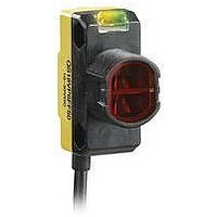
Figure 1. Features — fiber optic model shown
Figure 2. Dark sensing condition
Rear View
Indicators
Retroreflective Mode
Sensor
Condition
Output OFF
Output ON
Output ON,
Marginal Signal
Output Short
Circuit
Diffuse Mode
Front View
(Two LEDs: One Green, One Yellow)
Yellow Output LED
Green Power ON LED
Green
LED
ON
ON
ON
Flashing
No Target
Object
Present
Configuration
Push Button
Receiver Port
Emitter Port
Target
Object
Present
Target
Yellow
LED
OFF
ON
Flashing
OFF
Related parts for QS18EP6D
Image
Part Number
Description
Manufacturer
Datasheet
Request
R

Part Number:
Description:
Photoelectric Sensor
Manufacturer:
BANNER ENGINEERING
Datasheet:

Part Number:
Description:
Photoelectric Sensor
Manufacturer:
BANNER ENGINEERING
Datasheet:

Part Number:
Description:
LEDIR70XD4-XM-81039 MAX INTENS STROBE ONLY NO BANNER MARKS
Manufacturer:
BANNER ENGINEERING
Part Number:
Description:
M18SP6DL-72225 LABELED MOELLER NO BANNER MARKINGS BULK PACK
Manufacturer:
BANNER ENGINEERING
Part Number:
Description:
M18SP6DLQ-72226 LABLED MOELLER NO BANNER MARKINGS BULK PACK
Manufacturer:
BANNER ENGINEERING
Part Number:
Description:
M18SP6L-72223 LABELED MOELLER NO BANNER MARKINGS BULK PACK
Manufacturer:
BANNER ENGINEERING
Part Number:
Description:
M18SP6LQ-72224 LABELED MOELLER NO BANNER MARKINGS BULK PACK
Manufacturer:
BANNER ENGINEERING
Part Number:
Description:
P4D1-77908 P4 DRIVER GENERIC NO BANNER MARKINGS RESALE TO CUSTOMER
Manufacturer:
BANNER ENGINEERING
Part Number:
Description:
Photoelectric Sensor
Manufacturer:
BANNER ENGINEERING
Datasheet:

Part Number:
Description:
Programmable Indicator Light
Manufacturer:
BANNER ENGINEERING
Datasheet:
Part Number:
Description:
INDICATOR LED PANEL 50MM GRN/RED/YEL 30V
Manufacturer:
BANNER ENGINEERING
Datasheet:
Part Number:
Description:
Programmable Indicator Light
Manufacturer:
BANNER ENGINEERING
Datasheet: