QS18VN6LAF250Q BANNER ENGINEERING, QS18VN6LAF250Q Datasheet - Page 2
QS18VN6LAF250Q
Manufacturer Part Number
QS18VN6LAF250Q
Description
Photoelectric Sensor
Manufacturer
BANNER ENGINEERING
Series
QS18 Adjustable-Fieldr
Datasheet
1.QS18VN6AF100.pdf
(8 pages)
Specifications of QS18VN6LAF250Q
Output Current
100mA
Sensor Output
NPN
Supply Voltage Range Dc
10V To 30V
Sensing Range Min
0mm
Sensor Input
Laser
Supply Voltage Max
30VDC
Sensing Range Max
20mm


WORLD-BEAM
2
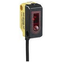
The QS18 Adjustable Field sensor is a full-featured sensor in a miniature package. It provides
background suppression sensing capability for small or difficult-to-reach areas. Models are
available with a visible red LED sensing beam, or one of two visible red lasers (see Models
table on page 1).
These adjustable-field sensors are able to detect objects of relatively low reflectivity, while
ignoring other objects in the background (beyond the cutoff point). The cutoff distance is
mechanically adjustable, using the 5-turn adjustment screw on the sensor top (Figure 1).
Backgrounds and background objects must always be placed beyond the cutoff distance.
Adjustable-Field Sensing – Theory of Operation
The sensor compares the reflections of its emitted light beam (E) from an object back to
the sensor’s two differently-aimed detectors R1 and R2 (see Figure 2). If the near detector
(R1) light signal is stronger than the far detector (R2) light signal (see object A, closer than
the cutoff distance), the sensor responds to the object. If the far detector (R2) light signal
is stronger than the near detector (R1) light signal (see object B, object beyond the cutoff
distance), the sensor ignores the object.
The cutoff distance for these sensors is adjustable. Objects lying beyond the cutoff distance
are ignored, even if they are highly reflective. However, it is possible to falsely detect a
background object, under certain conditions (see Background Reflectivity and Placement).
In the drawings and discussion on these pages, the letters E, R1, and R2 identify how the
sensor’s three optical elements (Emitter “E”, Near Detector “R1”, and Far Detector “R2”)
line up across the face of the sensor. The location of these elements defines the sensing
axis (see Figure 3). The sensing axis becomes important in certain situations, such as those
illustrated in Figures 7 and 8.
Setting the Cutoff Distance
The cutoff distance for the QS18AF models may be adjusted between 20 mm and
100 mm (0.8" to 4"); for QS18LAF models, between 30 mm and 150 mm (1.2" to 6"); and for
QS18LAF250 models, between 50 mm and 250 mm (2" to 10").
To properly set the cutoff point, position the lightest possible background to be used, at
the closest position it will come to the sensor during use. Using a small screwdriver in the
adjustment screw, adjust the cutoff distance until the threshold is reached and the yellow
Light Sensed indicator changes state. (If the indicator never comes ON, the background is
beyond the maximum sensing distance and will be ignored.) Repeat the procedure, using the
darkest target, placed in its most distant position for sensing. Adjust the cutoff approximately
midway between the two positions (Figure 4).
Sensing Reliability
For highest sensitivity, the sensor-to-object dis tance should be such that the object will
be sensed at or near the point of maximum excess gain. The excess gain curves on page
1 show excess gain vs. sensing distance for the minimum and maximum cutoff settings.
Maximum excess gain for model QS18VN6AF100 at a 20 mm cutoff occurs at a lens-to-object
distance of about 7 mm, for example. The background must be placed beyond the cutoff
distance; more reflective backgrounds should be placed even farther back. Following these
two guidelines will maximize sensing reliability.
P/N 66981 rev. G
®
QS18 Adjustable-Field Sensors
Sensor Setup
Overview
Banner Engineering Corp. • Minneapolis, MN U.S.A
www.bannerengineering.com • Tel: 763.544.3164
Figure 1. Sensor features
Figure 3. The sensing axis
Figure 2. Adjustable field sensing concept
Detector
Detector
Elements
Receiver
Flashes for Output Overload
Emitter
Near
Far
Light Sensed Indicator
Elements
Receiver
When an object approaches from the side,
the most reliable sensing usually occurs
when the line of approach is parallel to the
sensing axis.
R1
R2
Cutoff Point
Adjustment
E
Gain Conditions)
(Flashes for Low
Screw
Power Indicator
Lenses
Yellow:
Green:
Object
A
Sensing
Range
Sensing
Axis
Distance
Cutoff
Object B
or
Background
Related parts for QS18VN6LAF250Q
Image
Part Number
Description
Manufacturer
Datasheet
Request
R

Part Number:
Description:
Photoelectric Sensor
Manufacturer:
BANNER ENGINEERING
Datasheet:

Part Number:
Description:
Photoelectric Sensor
Manufacturer:
BANNER ENGINEERING
Datasheet:

Part Number:
Description:
LEDIR70XD4-XM-81039 MAX INTENS STROBE ONLY NO BANNER MARKS
Manufacturer:
BANNER ENGINEERING
Part Number:
Description:
M18SP6DL-72225 LABELED MOELLER NO BANNER MARKINGS BULK PACK
Manufacturer:
BANNER ENGINEERING
Part Number:
Description:
M18SP6DLQ-72226 LABLED MOELLER NO BANNER MARKINGS BULK PACK
Manufacturer:
BANNER ENGINEERING
Part Number:
Description:
M18SP6L-72223 LABELED MOELLER NO BANNER MARKINGS BULK PACK
Manufacturer:
BANNER ENGINEERING
Part Number:
Description:
M18SP6LQ-72224 LABELED MOELLER NO BANNER MARKINGS BULK PACK
Manufacturer:
BANNER ENGINEERING
Part Number:
Description:
P4D1-77908 P4 DRIVER GENERIC NO BANNER MARKINGS RESALE TO CUSTOMER
Manufacturer:
BANNER ENGINEERING
Part Number:
Description:
Photoelectric Sensor
Manufacturer:
BANNER ENGINEERING
Datasheet:

Part Number:
Description:
Programmable Indicator Light
Manufacturer:
BANNER ENGINEERING
Datasheet:
Part Number:
Description:
INDICATOR LED PANEL 50MM GRN/RED/YEL 30V
Manufacturer:
BANNER ENGINEERING
Datasheet:
Part Number:
Description:
Programmable Indicator Light
Manufacturer:
BANNER ENGINEERING
Datasheet: