QS30LLPQ BANNER ENGINEERING, QS30LLPQ Datasheet - Page 4
QS30LLPQ
Manufacturer Part Number
QS30LLPQ
Description
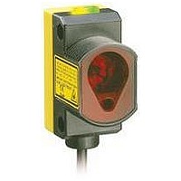
Photoelectric Sensor
Manufacturer
BANNER ENGINEERING
Datasheet
1.QS30LLP.pdf
(12 pages)
Specifications of QS30LLPQ
Sensing Range
0.2m To 18m
Output Current
150mA
Sensor Output
NPN/PNP
Supply Voltage Range Dc
10V To 30V
Sensor Housing
Rectangular
Sensing Range Min
0.2m
Sensor Input
Laser
Body Material
ABS Plastic


• Sets the sensor for maximum excess gain without allowing false proxing. Provides
• Useful for long-range applications and high variations in contrast, such as beam-
Sensor can be aimed at an object or the reflector during SET process to obtain the
same result. All conditions darker than the switchpoint condition result in ON output
(Dark Operate). Output ON and OFF conditions can be reversed by changing Light/Dark
Operate in SETUP mode (factory setting: Dark Operate).
Manual Adjust – Maximum Excess Gain SET
During RUN mode, adjusts switchpoint up or down via “+” or “–” push buttons.
• Each push button “click” adjusts the switchpoint up by approximately 0.5X excess
• The lighted bargraph LEDs move to reflect the increase or decrease of excess gain
• LEDs #7 and 8 flash when maximum gain is achieved; LEDs #1 and 2 flash when
When the received signal is at any level greater than 6X excess gain, the first “–”
(minus) click to reduce excess gain reduces it to the 6X level. Subsequent “–”
clicks result in decreased values as shown in the Specifications table on page 8
(approximately 2 clicks per LED change). To return to maximum excess gain, either
press “+” repeatedly until LEDs #7 and 8 flash, or hold the “+” button for longer than
2 seconds. For example, in an application that results in 20X excess gain, pressing “–”
once lowers the gain to 6X, exhibited by LED #8 ON. Pressing it twice more results
in approximately 5X excess gain, exhibited by LED #7 ON. Holding the “+” button for
2 seconds results in a return to maximum gain (20X), exhibited by LEDs #7 and 8
flashing.
WORLD-BEAM
4
maximum contrast between any reflector and a blocked condition and is stable even
in dirty environments.
break applications where the target objects are larger than the beam.
gain or down by the same increments.
relative to the switchpoint.
minimum gain is achieved.
P/N 112355 rev. A
• Press and hold “+”
> 2 seconds
Maximum Excess Gain SET – Model QS30LLP
Push Button
®
or
QS30 Series –
• Single-pulse remote line.
0.04 seconds ≤ T ≤ 0.8 seconds
Remote
T
T
Polarized Retroreflective Laser Sensors
T T T
T
T
Green Power LED: OFF
Yellow Output LED: ON
Bargraph: #7 & 8 flashing
• Sensor returns to RUN mode
• Use Manual Adjust to increase or
T
T
with new settings
decrease sensor excess gain
Banner Engineering Corp.
T
T
www.bannerengineering.com • Tel: 763.544.3164
T
T
Figure 3. Maximum Excess Gain SET (Dark
T
Darkest
(no signal)
T
Output ON
adjusted via Manual Adjust
Location of switchpoint
Indicators
Operate shown)
Factory-set
Threshold
•
Minneapolis, MN U.S.A.
Output OFF
—
GAIN
Most Light
(saturated
signal)
+
Related parts for QS30LLPQ
Image
Part Number
Description
Manufacturer
Datasheet
Request
R

Part Number:
Description:
Photoelectric Sensor
Manufacturer:
BANNER ENGINEERING
Datasheet:

Part Number:
Description:
Photoelectric Sensor
Manufacturer:
BANNER ENGINEERING
Datasheet:

Part Number:
Description:
LEDIR70XD4-XM-81039 MAX INTENS STROBE ONLY NO BANNER MARKS
Manufacturer:
BANNER ENGINEERING
Part Number:
Description:
M18SP6DL-72225 LABELED MOELLER NO BANNER MARKINGS BULK PACK
Manufacturer:
BANNER ENGINEERING
Part Number:
Description:
M18SP6DLQ-72226 LABLED MOELLER NO BANNER MARKINGS BULK PACK
Manufacturer:
BANNER ENGINEERING
Part Number:
Description:
M18SP6L-72223 LABELED MOELLER NO BANNER MARKINGS BULK PACK
Manufacturer:
BANNER ENGINEERING
Part Number:
Description:
M18SP6LQ-72224 LABELED MOELLER NO BANNER MARKINGS BULK PACK
Manufacturer:
BANNER ENGINEERING
Part Number:
Description:
P4D1-77908 P4 DRIVER GENERIC NO BANNER MARKINGS RESALE TO CUSTOMER
Manufacturer:
BANNER ENGINEERING
Part Number:
Description:
Photoelectric Sensor
Manufacturer:
BANNER ENGINEERING
Datasheet:

Part Number:
Description:
Programmable Indicator Light
Manufacturer:
BANNER ENGINEERING
Datasheet:
Part Number:
Description:
INDICATOR LED PANEL 50MM GRN/RED/YEL 30V
Manufacturer:
BANNER ENGINEERING
Datasheet:
Part Number:
Description:
Programmable Indicator Light
Manufacturer:
BANNER ENGINEERING
Datasheet: