S183E BANNER ENGINEERING, S183E Datasheet - Page 36
S183E
Manufacturer Part Number
S183E
Description
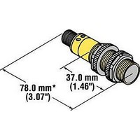
Photoelectric Sensor
Manufacturer
BANNER ENGINEERING
Type
Opposed Moder
Specifications of S183E
Output Current
150mA
Supply Voltage Range Dc
10V To 30V
Contact Current Max
300mA
Switch Terminals
Cable
Sensor Housing
Barrel
Sensor Input
Optical
Sensing Range Max
20m
Sensing Mode
Opposed
Brand/series
S18
Current, Switching
300 mA
Humidity
90% @ 50 °C (Non-Condensing)
Ip Rating
IP69K
Length, Cable
6.5 ft.
Material, Housing
PBT Polyester
Material, Lens
Polycarbonate⁄Acrylic
Output
SPST
Primary Type
Photoelectric
Range, Measurement
66 mm
Response Time
16 ms (ON), 8 ms (OFF)
Standards
CE Mark, CSA Certified, UL Listed
Technology
Photoelectric
Temperature, Operating
-40 to +70 °C
Termination
Cable
Vibration
10 to 60 Hz (Max.)
Voltage, Supply
250 VAC
Lead Free Status / Rohs Status
RoHS Exempt Product


100
T18 Series
Compact Sensors
Supply Voltage and Current
Supply Protection Circuitry
Output Configuration
Output Rating
Output Protection Circuitry
Output Response Time
Adjustments
Repeatability
Indicators
Construction
Environmental Rating
Connections
Operating Conditions
Vibration and
Mechanical Shock
Certifications
Hookup Diagrams
More information online at
10 to 30V dc (10% max. ripple); Supply current (exclusive of load current):
Opposed Mode Emitters: 25 mA
Polarized Retroreflective: 30 mA
Diffuse: 25 mA
Protected against reverse polarity and transient voltages
Solid-state complementary (SPDT) dc switch; NPN (current sinking) or PNP (current sourcing), depending on model.
The Dark Operate (DO) output may be wired as a normally open marginal signal alarm output, depending upon
hookup to the power supply.
150 mA max. (each) in standard hookup. When wired for alarm output, the total load may not exceed 150 mA;
Off-state leakage current: less than 1 mA at 30V dc;
On-state saturation voltage: less than 1V at 10 mA dc; <1.5V at 150 mA dc
Protected against false pulse on power-up and continuous overload or short circuit of outputs
Opposed: 3 milliseconds ON, 1.5 milliseconds OFF; Polarized Retroreflective, Non-polarized Retroreflective,
Fixed-field and Diffuse: 3 milliseconds ON/OFF
NOTE: 100 millisecond delay on power-up; outputs are non-conducting during this time
T18 Series infrared non-polarized retroreflective and diffuse mode models (only) have a single-turn rear-panel
SENSITIVITY control for adjustment of system gain (turn clockwise to increase)
Opposed: 375 microseconds; Polarized Retroreflective, Non-polarized Retroreflective, Fixed-field and
Diffuse: 750 microseconds. Repeatability and response are independent of signal strength.
Two LEDs: Green and Yellow
Housings are thermoplastic polyester. Lenses are polycarbonate or acrylic; one jam nut included
Leakproof design rated NEMA 6P, DIN 40050 (IP69K)
2 m or 9 m attached cable, or 4-pin Euro-style quick-disconnect fitting. QD cables are ordered separately. See page 380.
Temperature: -40° to +70° C
All models meet Mil. Std. 202F requirements. Method 201A (Vibration; frequency 10 to 60 Hz, max., double
amplitude 0.06-inch acceleration 10G). Method 213B conditions H&I (Shock: 75G with unit operating; 100G for
non-operation)
Emitters: DC03 (p. 476)
bannerengineering.com
Green ON steady: power to sensor is ON
Green flashing: output is overloaded (dc models only)
Yellow ON steady: Light Operate (LO) output is energized
Yellow flashing: excess gain marginal (1-1.5x) in light condition, LO output is energized
T18 DC Specifications
R
NPN Models: DC07 (p. 477)
Relative humidity: 90% at 50° C (non-condensing)
Opposed Mode Receivers: 20 mA
Non-polarized Retroreflective: 25 mA
Fixed-field: 35 mA
PNP Models: DC08 (p. 477)
Related parts for S183E
Image
Part Number
Description
Manufacturer
Datasheet
Request
R

Part Number:
Description:
S18 Sensors ? Dc-Voltage Series
Manufacturer:
BANNER ENGINEERING
Datasheet:

Part Number:
Description:
S18AW3RQ1 AC LO RCVR QD
Manufacturer:
BANNER ENGINEERING
Datasheet:
Part Number:
Description:
S18SN6FF50 DC NPN LO 50MM FF
Manufacturer:
BANNER ENGINEERING
Datasheet:
Part Number:
Description:
S18SN6L LO DC NPN RETRO COMMOD
Manufacturer:
BANNER ENGINEERING
Datasheet:
Part Number:
Description:
S18SP6DL LO DC PNP LR DIFFUSE
Manufacturer:
BANNER ENGINEERING
Datasheet:
Part Number:
Description:
S18SP6FF50 DC PNP LO 50MM FF
Manufacturer:
BANNER ENGINEERING
Datasheet:
Part Number:
Description:
S18SP6L LO DC PNP RETRO COMMOD
Manufacturer:
BANNER ENGINEERING
Datasheet:
Part Number:
Description:
S18SP6LQ LO DC PNP RETRO COMOD
Manufacturer:
BANNER ENGINEERING
Datasheet:
Part Number:
Description:
SENSOR; PHOTOELECTRIC; 18MM PLASTIC; DIFFUSE; INFRARED; RANGE 300MM; NPN; 10-30V
Manufacturer:
BANNER ENGINEERING
Datasheet:

Part Number:
Description:
Photoelectric Sensor
Manufacturer:
BANNER ENGINEERING
Datasheet:

Part Number:
Description:
Programmable Indicator Light
Manufacturer:
BANNER ENGINEERING
Datasheet:
Part Number:
Description:
INDICATOR LED PANEL 50MM GRN/RED/YEL 30V
Manufacturer:
BANNER ENGINEERING
Datasheet:
Part Number:
Description:
Programmable Indicator Light
Manufacturer:
BANNER ENGINEERING
Datasheet: