S18SN6FF50Q BANNER ENGINEERING, S18SN6FF50Q Datasheet - Page 21
S18SN6FF50Q
Manufacturer Part Number
S18SN6FF50Q
Description
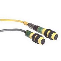
Photoelectric Sensor
Manufacturer
BANNER ENGINEERING
Type
Fixed Fieldr
Specifications of S18SN6FF50Q
Output Current
150mA
Sensor Output
NPN
Supply Voltage Range Dc
10V To 30V
Sensing Range Max
25mm
Leaded Process Compatible
No
Peak Reflow Compatible (260 C)
No
Sensor Input
Laser
Primary Type
Photoelectric


*
** For 9 m cable, add suffix W/30 to the 2 m model number (example, SMU315F W/30).
MINI-BEAM
SMU315F
SMU315FV
SMU315FP
Supply Voltage
Supply Protection Circuitry
Output Configuration
Output Rating
Output Protection Circuitry
Output Response Time
Repeatability
Adjustments
Indicators
Construction
Environmental Rating
Connections
Operating Conditions
Application Notes
Certifications
Hookup Diagrams
Models
Infrared LED
®
PLASTIC FIBER
MINI-BEAM
GLASS FIBER
GLASS FIBER
Mode/LED*
Universal Voltage, 24-240V ac or dc
Sensing
Visible Red LED
Max. switching power (resistive load): 90W, 250VA
Universal voltage: 24 to 240V ac, 50/60Hz or
Protected against transient voltages. DC hookup is without regard to polarity.
SPDT (Single-Pole, Double Throw) (form C) electromechanical relay, ON/OFF output.
Max. switching voltage (resistive load): 250V ac or 30V dc
Max. switching current (resistive load): 3A
Min. voltage and current: 5V dc, 10 mA
Mechanical life: 20,000,000 operations
Electrical life at full resistive load: 100,000 operations
Protected against false pulse on power-up.
Closure time: 20 milliseconds max.
Release time: 20 milliseconds max.
Max. switching speed: 25 operations per second
All sensing modes: 1 millisecond
Light/Dark Operate select switch, and 15-turn slotted brass screw Gain (sensitivity) adjustment potentiometer
(clutched at both ends of travel). Both controls are located on rear panel of sensor and are protected by a gasketed,
clear acrylic cover.
Alignment Indicator Device system (AID) lights a rear-panel-mounted LED indicator whenever the sensor sees a
“light” condition, with a superimposed pulse rate proportional to the light signal strength (the stronger the signal,
the faster the pulse rate).
Reinforced thermoplastic polyester housing, totally encapsulated, o-ring seal, acrylic lenses, and stainless steel screws.
Meets NEMA standards 1, 2, 3, 3S, 4, 4X, 6, 12, and 13; IEC IP67.
PVC-jacketed 5-conductor 2 m or 9 m unterminated cable. Opposed mode emitter cables are 2-conductor.
Temperature: -20° to +55° C
Install transient suppressor (MOV) across contacts switching inductive loads.
Emitters: UN02 (p. 487)
Range varies
Range varies
fiber optics
fiber optics
by sensing
by sensing
mode and
mode and
Range
used
used
®
Universal Voltage Specifications
24 to 240V dc (1.5 watts or 2.5 VA max.)
Other AC/DC Models: UN01 (p. 487)
Cable**
Relative humidity: 90% at 50° C (non-condensing)
More information online at
2 m
2 m
2 m
MINI-BEAM
E/M Relay
Output
SPDT
Type
bannerengineering.com
(cont’d)
®
EGCG-18 &
EGCP-12 &
(p. 444) &
EGCG-16
EGCG-17
EGCG-19
EGCP-13
(p. 445)
(p. 445)
(p. 447)
Excess
Universal Voltage Series
Gain
(p. 462) &
BPG-18 &
BPP-12 &
Pattern
(p. 463)
(p. 463)
(p. 465)
BPG-16
BPG-17
BPG-19
BPP-13
Beam
Compact Sensors
Sheet
55230
Data
Download
PDF
85
Related parts for S18SN6FF50Q
Image
Part Number
Description
Manufacturer
Datasheet
Request
R

Part Number:
Description:
Photoelectric Sensor
Manufacturer:
BANNER ENGINEERING
Datasheet:

Part Number:
Description:
Photoelectric Sensor
Manufacturer:
BANNER ENGINEERING
Datasheet:

Part Number:
Description:
LEDIR70XD4-XM-81039 MAX INTENS STROBE ONLY NO BANNER MARKS
Manufacturer:
BANNER ENGINEERING
Part Number:
Description:
M18SP6DL-72225 LABELED MOELLER NO BANNER MARKINGS BULK PACK
Manufacturer:
BANNER ENGINEERING
Part Number:
Description:
M18SP6DLQ-72226 LABLED MOELLER NO BANNER MARKINGS BULK PACK
Manufacturer:
BANNER ENGINEERING
Part Number:
Description:
M18SP6L-72223 LABELED MOELLER NO BANNER MARKINGS BULK PACK
Manufacturer:
BANNER ENGINEERING
Part Number:
Description:
M18SP6LQ-72224 LABELED MOELLER NO BANNER MARKINGS BULK PACK
Manufacturer:
BANNER ENGINEERING
Part Number:
Description:
P4D1-77908 P4 DRIVER GENERIC NO BANNER MARKINGS RESALE TO CUSTOMER
Manufacturer:
BANNER ENGINEERING
Part Number:
Description:
Photoelectric Sensor
Manufacturer:
BANNER ENGINEERING
Datasheet:

Part Number:
Description:
Programmable Indicator Light
Manufacturer:
BANNER ENGINEERING
Datasheet:
Part Number:
Description:
INDICATOR LED PANEL 50MM GRN/RED/YEL 30V
Manufacturer:
BANNER ENGINEERING
Datasheet:
Part Number:
Description:
Programmable Indicator Light
Manufacturer:
BANNER ENGINEERING
Datasheet: