S51-PA-5-C10-PK IDEC, S51-PA-5-C10-PK Datasheet - Page 22
S51-PA-5-C10-PK
Manufacturer Part Number
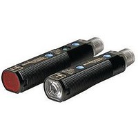
S51-PA-5-C10-PK
Description
Photoelectric Sensor
Manufacturer
IDEC
Datasheet
1.95ACC1380.pdf
(26 pages)
Specifications of S51-PA-5-C10-PK
Sensing Range
0cm To 10cm
Output Current
100mA
Sensor Output
PNP
Supply Voltage Range Dc
10V To 30V
Sensor Housing
Cylinder Rotatable
Sensing Range Min
0cm
Sensor Input
Optical
Sensing Range Max
10cm
Lead Free Status / RoHS Status
Lead free / RoHS Compliant


Sensors
Specifi cations
Do not operate a sensor under any conditions exceeding these specifi cations.
Do not operate a sensor under current and voltage conditions other than those
for which the individual sensor is rated.
Do not exceed the recommended operating temperature and humidity. Although
sensors are rated for operation below 0°C, this specifi cation does not imply
that performance characteristics will remain constant under prolonged freezing
conditions. Continued exposure and the accompanying frost, ice, dew, and con-
densation which accumulate on the optical surface will adversely affect sensor
performance.
To maintain performance characteristics, do not exceed vibration and shock
resistance ratings while operating a sensor. In addition, avoid impacts to the
sensor housing which are severe enough to adversely affect the waterproof
characteristics.
IEC (International Electrotechnical Commission) Ratings
Sensors rated IP67 are resistant to moisture when occasionally immersed in
water. Sensors rated IP64 through IP66 are resistant to moisture when occasion-
ally subjected to splashing or when located in the vicinity of turbulent waters.
These ratings do not imply that a sensor is intended for use under continual
high-pressure water spray. Avoid such applications to maintain optimal sensor
performance.
Sensors rated IP64 through IP67 are dust-tight and water-tight. For best perfor-
mance, avoid using any sensor in an area where it will be subjected to heavy
particle blasts and where dust, water, or steam will accumulate on the optical
surface.
Start-up
Do not test the housing for dielectric strength and insulation resistance, since
the housing is connected to the electronic circuit ground of a sensor. Do not
perform dielectric strength and insulation resistance tests on electrical systems
without disconnecting photoelectric sensors, as such testing may result in dam-
age to the sensor.
Several lines of sensors, as noted in the individual operation sections, are pro-
vided with an internal circuit to turn an output off for a specifi ed amount of time
upon power-up. This delay is normal; it prevents a transient state when turning
power on.
Optimum Performance
The optical surface of each sensor must be cleaned on a regular basis for
continual superior performance. Use a soft cloth dipped in isopropyl alcohol to
remove dust and moisture build-up.
IMPORTANT: Do not use organic solvents (such as thinner, ammonia, caustic
soda, or benzene) to clean any part of a sensor.
All sensors experience signal inconsistencies under the infl uence of inductive
noise. Do not use sensors in close proximity to transformers, large inductive
motors or generators. Avoid using sensors in direct contact with sources of
excessive heat. Also avoid operation in close proximity to welding equipment.
It is strongly recommended to avoid using any sensor where it will be continually subjected to elements which
impair performance or cause corrosive damage to the sensor. In particular, avoid strong vibrations and
shocks, corrosive gases, oils and chemicals, as well as blasts of water, steam, dust or other particles.
USA: 800-262-IDEC
General Information
Canada: 888-317-IDEC
Light
Visible light is electromagnetic radiation with a wavelength be-
tween 390 and 770nm. White light is composed of all the vis-
ible spectrum components in equal quantity; the predominance of
a specifi c wavelength determines the color of the light. Light Emit-
ting Diodes (LEDs) are the most common light used in optoelectronics.
Transmission, Absorption, Refl ection
When light hits an object three things
take place at the same time: refl ection
( ), absorption ( ) and transmis-
sion ( ); with parameters and ratios
that vary according to the object
themselves, which are then further
differentiated by material, surface, thickness and/or color. These elements can
be detected using a photoelectric sensor.
Extraneous Light
Bright, extraneous light such as sunlight, incandescent lights, or fl uorescent
lights may impair the performance of sensors in detecting color or light.
Make sure that extraneous light does not exceed recommended levels found in
the individual specifi cations sections. When 500 lux is specifi ed, this is equal to
50 footcandles. The average factory illumination is ordinarily below this level,
except in areas where visual inspection is being performed. Only in such brightly
lit areas is incident light of particular concern.
Unwanted light interference can often be avoided simply by making sure that the
optical receiver is not aimed directly toward a strong light source. When mount-
ing direction cannot be adjusted, place a light barrier between all nearby light
sources and the receiver.
Through-beam Sensors
receiver; each object that interrupts the beam is detected. This system is used to
obtain large signal differences
(when the light directly hits the
receiver and when the object
interrupts the beam) with the
highest Excess Gain and the
largest operating distance reaching
up to 50m. These sensors can
operate in the harshest environ-
mental conditions, such as in the
presence of dirt or dust. The disadvantage is that two units have to be wired (an
emitter and receiver). The through-beam optic function operates typically in dark
mode: the output is activated when the object interrupts the beam between the
emitter and receiver.
With through-beam sensors, the light emitter and receiver are
contained in two different housings that are mounted one in front of
the other. The light beam emitted by the emitter directly hits the
General Information
233
Related parts for S51-PA-5-C10-PK
Image
Part Number
Description
Manufacturer
Datasheet
Request
R

Part Number:
Description:
SENSOR; PHOTOELECTRIC; DIFFUSED; M12
Manufacturer:
IDEC Corporation
Datasheet:
Part Number:
Description:
SENSOR; PHOTOELECTRIC; THROUGH BEAM RECEIVER; M12
Manufacturer:
IDEC Corporation
Datasheet:
Part Number:
Description:
SENSOR; PHOTOELECTRIC; POLARIZED; RETRO-REFLECTIVE; M12
Manufacturer:
IDEC Corporation
Datasheet:
Part Number:
Description:
SENSOR; PHOTOELECTRIC; THROUGH BEAM EMMITER; M12
Manufacturer:
IDEC Corporation
Datasheet:
Part Number:
Description:
SENSOR; PHOTOELECTRIC; RETRO-REFLECTIVE; M12
Manufacturer:
IDEC Corporation
Datasheet:
Part Number:
Description:
SENSOR; PHOTOELECTRIC; THROUGH BEAM RECEIVER; M12
Manufacturer:
IDEC Corporation
Datasheet:

Part Number:
Description:
Photoelectric Sensor
Manufacturer:
IDEC
Datasheet:
Part Number:
Description:
Photoelectric Sensor
Manufacturer:
IDEC
Datasheet:
Part Number:
Description:
Photoelectric Sensor
Manufacturer:
IDEC
Datasheet:
Part Number:
Description:
Photoelectric Sensor
Manufacturer:
IDEC
Datasheet:
Part Number:
Description:
INDICATOR INCANDESCENT LAMP, GREEN
Manufacturer:
IDEC
Datasheet:

Part Number:
Description:
LAMP, INDICATOR, INCAND, AMB
Manufacturer:
IDEC
Datasheet:
Part Number:
Description:
LAMP, INDICATOR, INCAND, GRN
Manufacturer:
IDEC
Datasheet:
Part Number:
Description:
LAMP, INDICATOR, INCAND, GRN
Manufacturer:
IDEC
Datasheet:
Part Number:
Description:
LAMP, INDICATOR, INCANDESCENT, RED
Manufacturer:
IDEC
Datasheet: