SA1E-TP1-2M IDEC, SA1E-TP1-2M Datasheet - Page 6
SA1E-TP1-2M
Manufacturer Part Number
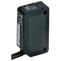
SA1E-TP1-2M
Description
Photoelectric Sensor
Manufacturer
IDEC
Datasheet
1.SA9Z-K01.pdf
(7 pages)
Specifications of SA1E-TP1-2M
Sensing Range
0m To 10m
Output Current
20mA
Sensor Output
PNP LO
Supply Voltage Range Dc
10V To 30V
Sensing Range Max
10m
Sensing Mode
Through-Beam
Switch Features
Light On
Rohs Compliant
Yes
Lead Free Status / RoHS Status
Lead free / RoHS Compliant


Do not operate a sensor under any conditions exceeding these specifications.
Do not operate a sensor under current and voltage conditions other than
those for which the individual sensor is rated.
Do not exceed the recommended operating temperature and humidity.
Although sensors are rated for operation below 0°C, this specification does
not imply that performance characteristics will remain constant under pro-
longed freezing conditions. Continued exposure and the accompanying frost,
ice, dew, and condensation which accumulate on the optical surface will
adversely affect sensor performance.
To maintain superior performance characteristics, do not exceed vibration and
shock resistance ratings while operating a sensor. In addition, avoid isolated
impacts to the sensor housing which are severe enough to adversely affect
the waterproof characteristics.
Sensors rated IP67 are resistant to moisture when occasionally immersed in
still water. Sensors rated IP64 through IP66 are resistant to moisture when
occasionally subjected to splashing or when located in the vicinity of turbu-
lent waters. These ratings do not imply that a sensor is intended for use
under continual high-pressure water spray. Avoid such applications to main-
tain optimal sensor performance.
Sensors rated IP64 through IP67 are dust-tight and water-tight. For best per-
formance, avoid using any sensor in an area where it will be subjected to
heavy particle blasts and where dust, water, or steam will accumulate on the
optical surface.
Do not test the housing for dielectric strength and insulation resistance, since
the housing is connected to the electronic circuit ground of a sensor. Do not
perform dielectric strength and insulation resistance tests on electrical sys-
tems without disconnecting photoelectric sensors, as such testing may result
in damage to the sensor.
Several lines of sensors, as noted in the individual operation sections, are
provided with an internal circuit to turn an output off for a specified amount of
time upon power-up. This delay is normal; it prevents a transient state when
turning power on.
The optical surface of each sensor must be cleaned on a regular basis for con-
tinual superior performance. Use a soft cloth dipped in isopropyl alcohol to
remove dust and moisture build-up.
IMPORTANT: Do not use organic solvents (such as thinner, ammonia, caustic
soda, or benzene) to clean any part of a sensor.
All sensors experience signal inconsistencies under the influence of inductive
noise. Do not use sensors in close proximity to transformers, large inductive
motors, or generators. Avoid using sensors in direct contact with sources of
excessive heat. Also avoid operation in close proximity to welding equipment.
www.idec.com
1.
2.
IEC
mance or cause corrosive damage to the sensor. In particular, avoid strong vibrations and shocks, corrosive gases, oils, and chemi-
cals, as well as blasts of water, steam, dust, or other particles.
(International Electrotechnical Commission)
Even though the SA6A ultrasonic sensor features protection against noise, there may be adverse effects from strong noise.
It is strongly recommended to avoid using any sensor where it will be continually subjected to elements which impair perfor-
Optimum Performance
Sensors
Specifications
Start-up
USA: (800) 262-IDEC or (408) 747-0550, Canada: (888) 317-IDEC
Ratings
General Information
Bright, extraneous light such as sunlight, incandescent lights, or fluorescent
lights may impair the performance of sensors in detecting color or light.
Make sure that extraneous light does not exceed recommended levels found
in the individual specifications sections. When 500 lux is specified, this is
equal to 50 footcandles. The average factory illumination is ordinarily below
this level, except in areas where visual inspection is being performed. Only in
such brightly lit areas is incident light of particular concern.
Unwanted light interference can often be avoided simply by making sure that
the optical receiver is not aimed directly toward a strong light source. When
mounting direction cannot be adjusted, place a light barrier between all
nearby light sources and the receiver.
When installing sensors which detect reflected light, make sure that
unwanted light reflections from nearby surfaces, such as the floor, walls,
reflective machinery, or stainless steel, do not reach the optical receiver.
Also, make sure that reflected-light sensors mounted in close proximity do not
cause interfering reflections. When it is not possible to maintain the recom-
mended clearance between sensors, as noted in the individual installation
sections, provide light barriers between sensors.
A slit attachment is available to modify the beam size of through-beam sen-
sors. This option is recommended for detecting very small objects (near the
size of the smallest object which a sensor can detect) or for eliminating light
interference when sensors are mounted in close proximity.
IMPORTANT: Always consider safety when installing a laser sensor of any kind.
Make sure that the laser beam cannot inadvertently shine into the eyes of people
passing by or working in the vicinity. See safety information on page Q-20.
The mounting bracket and hardware are included with sensors, where appli-
cable. Use the appropriate hardware for mounting, along with washers and
spring washers or lock nuts. Do not overtighten attachment hardware. Over-
tightening causes damage to the housing and will adversely affect the water-
proof characteristics of the sensor.
Best results can be obtained when the sensor is mounted so that the object
sensed is in the center of the beam, rather than when the object is located
near the edges of the sensing window. In addition, the most reliable sensing
occurs when the majority of the objects being sensed are well within the
sensing range, rather than at the extreme near and far limits.
3. SA6A ultrasonic sensors are not affected by extraneous light.
Reflected-Light Sensors
Through-Beam Sensors
Extraneous Light
Laser Sensors
Mounting
General Information
Q-55
Q
Related parts for SA1E-TP1-2M
Image
Part Number
Description
Manufacturer
Datasheet
Request
R

Part Number:
Description:
Sensor, Photoelectric, Background Suppression, Red LED, PNP Output, 20-200mm Range
Manufacturer:
IDEC Corporation
Datasheet:
Part Number:
Description:
SENSOR, PHOTOELECTRIC, PNP OUTPUT, DIFFUSE-REFLECTIVE TYPE, INFRARED LED, W/SENSI
Manufacturer:
IDEC Corporation
Datasheet:
Part Number:
Description:
SENSOR, PHOTOELECTRIC, NPN OUTPUT, POLARIZED RETROREFLECTIVE TYPE, RED LED, W/SEN
Manufacturer:
IDEC Corporation
Datasheet:
Part Number:
Description:
SENSOR, PHOTOELECTRIC, PNP OUTPUT, THROUGH-BEAM TYPE, INFRARED LED, W/SENSITIVITY
Manufacturer:
IDEC Corporation
Datasheet:
Part Number:
Description:
Sensor, Photoelectric, Background Suppression, Red LED, NPN Output, 20-200mm Range
Manufacturer:
IDEC Corporation
Datasheet:
Part Number:
Description:
SENSOR, PHOTOELECTRIC, PNP OUTPUT, DIFFUSE-REFLECTIVE TYPE, INFRARED LED, W/SENSI
Manufacturer:
IDEC Corporation
Datasheet:
Part Number:
Description:
SENSOR, PHOTOELECTRIC, NPN OUTPUT, DIFFUSE-REFLECTIVE TYPE, INFRARED LED, W/SENSI
Manufacturer:
IDEC Corporation
Datasheet:
Part Number:
Description:
SENSOR, PHOTOELECTRIC, NPN OUTPUT, DIFFUSE-REFLECTIVE TYPE, INFRARED LED, W/SENSI
Manufacturer:
IDEC Corporation
Datasheet:
Part Number:
Description:
SENSOR, PHOTOELECTRIC, PNP OUTPUT, POLARIZED RETROREFLECTIVE TYPE, RED LED, W/SEN
Manufacturer:
IDEC Corporation
Datasheet:
Part Number:
Description:
SENSOR, PHOTOELECTRIC, PNP OUTPUT, DIFFUSE-REFLECTIVE TYPE, INFRARED LED, W/SENSI
Manufacturer:
IDEC Corporation
Datasheet:
Part Number:
Description:
INDICATOR INCANDESCENT LAMP, GREEN
Manufacturer:
IDEC
Datasheet:

Part Number:
Description:
LAMP, INDICATOR, INCAND, AMB
Manufacturer:
IDEC
Datasheet:
Part Number:
Description:
LAMP, INDICATOR, INCAND, GRN
Manufacturer:
IDEC
Datasheet:
Part Number:
Description:
LAMP, INDICATOR, INCAND, GRN
Manufacturer:
IDEC
Datasheet:
Part Number:
Description:
LAMP, INDICATOR, INCANDESCENT, RED
Manufacturer:
IDEC
Datasheet: